Custom Robot Workstations And Laser Systems Manufacturer


3D Vision Laser Seam Tracking Explained:From Point Cloud to Weld Path in Seconds
Ask most people how a robot knows where to weld and they describe a programmer with a teach pendant, guiding the arm point by point through a path stored in the controller. That model is forty years old. The technology that has replaced it — 3D laser seam tracking — does in seconds what a programmer used to spend hours doing, and it does it more accurately, because it reads the actual part rather than a memorised ideal.
This article explains how 3D vision laser seam tracking works from first principles: how the scanner captures a point cloud, how the software extracts the weld seam from that cloud, and how the system converts seam geometry into a robot weld path — all without human intervention. It is written for engineers and production managers evaluating whether this technology fits their structural steel fabrication environment.
Why Seam Tracking Exists — and What It Replaces
Traditional robotic welding assumes the part is exactly where the program says it is. The weld path is taught against an ideal part in a precise fixture, then replayed on every subsequent part. That assumption works well in automotive manufacturing, where stamped parts hold tolerances of ±0.3 mm and fixtures are engineered to repeat at the same level.
It does not work in structural steel fabrication. Flame-cut and saw-cut plate tolerances are ±1–3 mm. Fit-up gaps vary from one end of a joint to the other. Parts loaded by crane sit slightly differently every cycle. A fixed programmed path on structural steel produces inconsistent weld throat size, missed joints, and rework rates that eliminate the productivity gain of automation.
Seam tracking solves this by moving the intelligence from the program to the sensor. Instead of trusting a stored position, the system reads the actual joint geometry before — and during — every weld. The path follows the real seam, not the theoretical one.
| The core shift: traditional robotic welding trusts the program.3D vision seam tracking trusts the part. |
What Is 3D Vision Laser Seam Tracking?
| 3D vision laser seam tracking is a sensing and software system that uses a laser profiler orstructured-light scanner to capture the three-dimensional geometry of a weld joint, extract theseam centreline and gap parameters from that data, and continuously update the robot’s weldpath to follow the actual joint — compensating for part variation, fit-up gaps, and thermaldistortion in real time. |
There are two distinct applications of this technology, and it is worth being precise about both.
Pre-weld scanning (path planning): the scanner sweeps the joint before welding begins, the software generates the complete robot trajectory from the scan data, and the robot then executes that path. This is the approach used in no-programming cells to eliminate teach pendant programming entirely.
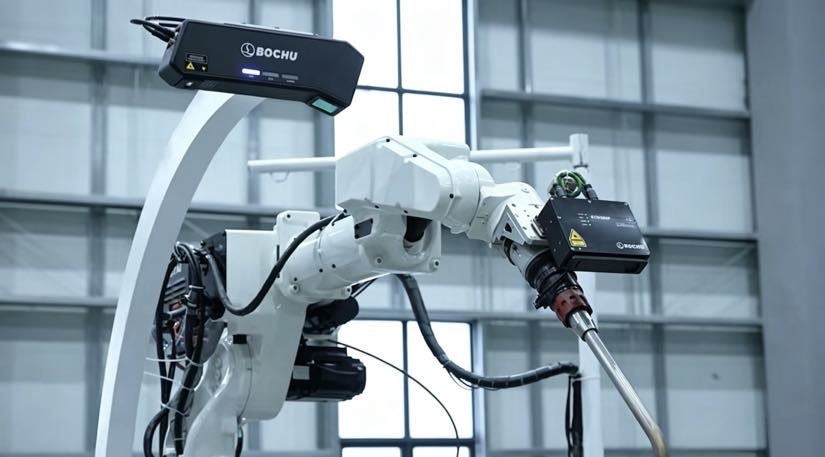
In-weld tracking (real-time correction): a sensor mounted close to the torch monitors the joint continuously during welding and feeds correction signals to the robot controller, adjusting torch position in real time as the seam deviates from the planned path. This compensates for thermal distortion and fixturing drift that occur after the pre-weld scan.
Most capable modern systems combine both: pre-weld scanning generates the initial path, and in-weld tracking refines it continuously throughout the weld pass. Our intelligent welding system uses this combined approach — high-speed 3D laser pre-weld profiling for path generation, plus continuous arc tracking during execution.
From Point Cloud to Weld Path — The Technical Process
Understanding the process in sequence makes it clear why this technology is reliable enough for structural steel production — and where its limits lie.
Step 1: Light projection and reflection capture
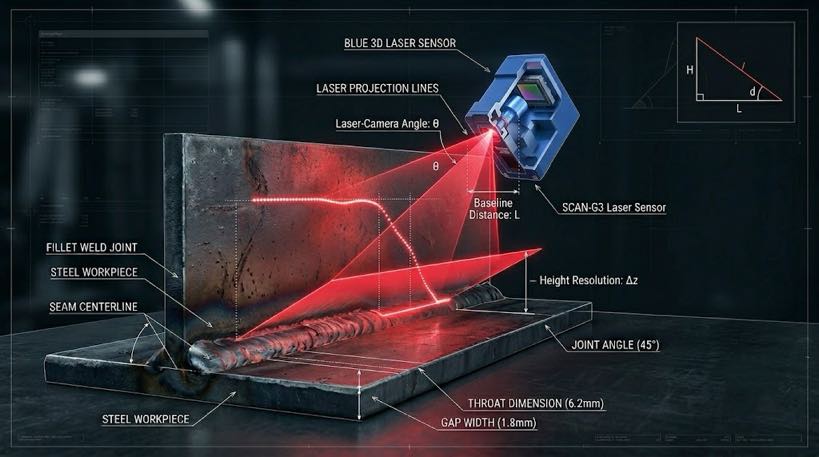
The scanner projects a structured pattern of laser light — typically a line or a grid — across the weld joint surface. A camera offset from the laser source captures the reflected pattern. Because the camera and laser are at a fixed angle to each other (a geometry called laser triangulation), any deviation in surface height causes a predictable shift in where the reflected line appears in the camera image.
The system measures these shifts across the full width of the scan and converts them into a height map of the joint surface. Our 3D laser profiler captures this data at up to 1,140 frames per second across a 2,600 mm field of view — fast enough to scan a full structural beam in a single sweeping pass without stopping.
Step 2: Point cloud construction
As the scanner moves along the joint (either the scanner moves, or the robot carries it, or the part moves on a positioner), successive height profiles are assembled into a three-dimensional point cloud — a dense array of x, y, z coordinate measurements representing the joint surface geometry.
Resolution matters here. At 0.2–0.5 mm point spacing, the cloud captures the fine geometry of a weld groove — root face, bevel angle, land, gap width — with sufficient precision to plan a weld path that will meet AWS D1.1 dimensional requirements. Lower-resolution scanners miss groove geometry detail and produce paths that require correction.
| Point cloud quality check — what good data looks like: Point spacing: 0.2–0.5 mm (sufficient for structural MIG weld joints) Scan speed: Covers 1 m of weld joint in < 90 seconds at production pace Noise level: < 0.1 mm Z-axis noise at rated scan distance Field of view: Wide enough to capture both sides of the joint in one pass |
Step 3: Seam extraction
Raw point cloud data contains the entire scanned surface — base plate, weld prep, tack welds, surrounding structure. The seam extraction algorithm must identify the weld joint from this background.
The algorithm looks for geometric features characteristic of each joint type. For a fillet weld, it finds the intersection of two planar surfaces. For a butt weld with a V-groove, it identifies the valley between two bevelled edges. For a T-joint, it finds the root point where vertical web meets horizontal flange. Once the joint feature is located, the algorithm fits a centreline and extracts key parameters:
- Joint centreline position (x, y, z coordinates along the full joint length)
- Root gap width at each point along the joint
- Bevel angle and root face geometry (for groove welds)
- Throat depth or leg length target based on joint geometry
- Any geometric anomalies — bridging tack welds, local gap spikes, missing material
Tack welds present a specific challenge: they cross the seam and can confuse the extraction algorithm if their height is large relative to the gap. Capable systems detect tack welds as anomalies and either skip them in the path or reduce travel speed to weld over them correctly. The operator is notified if a tack exceeds the system’s compensation range.
Step 4: Path planning and trajectory generation
With the seam geometry extracted, the path planning module generates the complete robot motion sequence. This is more complex than simply following the centreline — the system must also plan:
- Torch angle relative to the joint (work angle and travel angle for fillet welds)
- Approach and retract paths that avoid collision with the workpiece and fixture
- Weave parameters if the gap requires oscillation to fill it
- Multi-pass sequence if throat size exceeds single-pass limits (typically > 8 mm fillet)
- Interpass positioning for the positioner if the part needs to be rotated between passes
The generated trajectory is a time-stamped sequence of robot joint positions, torch angles, and weld parameter calls — a complete weld program, generated in 15–45 seconds from scan data, with no human input.
| Time to first arc on a new part type: Traditional teach pendant: 2–8 hours programming Offline programming (OLP): 45 minutes – 3 hours 3D vision path planning: < 5 minutes total (scan + extract + generate) |
Step 5: In-weld real-time correction
Pre-weld scanning captures the joint geometry before thermal effects begin. Once the arc opens, two things change: the workpiece heats up and distorts, and the weld pool position relative to the joint shifts slightly with each pass. In-weld tracking handles this.
A sensor — either a small laser profiler mounted near the torch, or arc-based sensing using the welding current itself — monitors the seam position continuously during the weld pass. Correction signals are sent to the robot controller at update rates of 50–200 Hz, nudging the torch position to stay on the centreline as the part moves under heat.
The intelligent welding system’s proprietary arc tracking algorithm maintains seam accuracy at oscillation amplitudes as fine as 1 mm — which means it can follow the seam even during weave welding on a thermally distorted thin plate, where the seam position shifts continuously as each bead deposits heat.
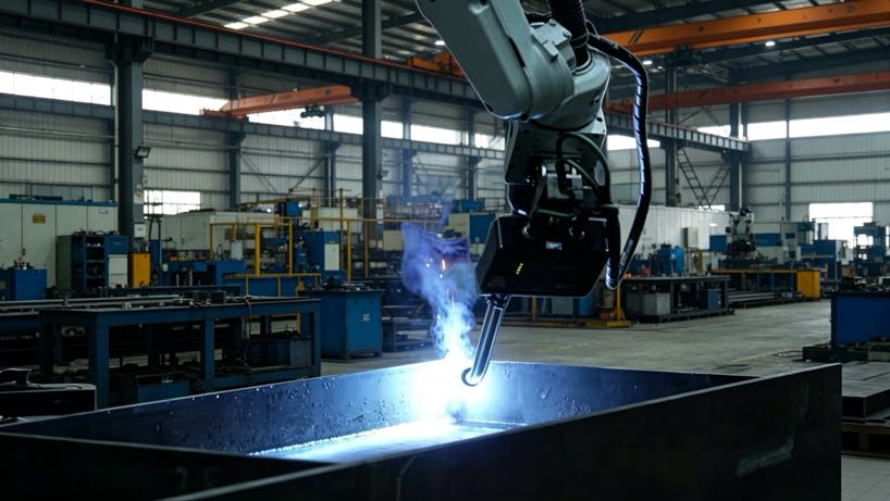
Scanner Technology: Laser Triangulation vs Structured Light
Two sensing technologies dominate industrial weld seam scanning. Understanding their differences helps when evaluating competing systems.
| Characteristic | Laser line triangulation | Structured light (fringe projection) |
| Principle | Single laser line swept across surface | Grid or fringe pattern projected on surface |
| Speed | Very fast — 1,000+ fps line rate | Slower — multiple exposures per frame |
| Resolution | High in one axis; depends on scan speed in other | High in both axes simultaneously |
| Stand-off distance | Typically 100–400 mm | Typically 200–600 mm |
| Performance on shiny surfaces | Can be affected by specular reflection | More robust on reflective metal |
| Best fit for welding | In-weld tracking + pre-weld line scanning | Pre-weld full-surface scanning |
| Our intelligent welding system | High-speed laser profiler at 1,140 fps for pre-weld scanning + arc tracking | Large line-scan camera for global positioning |
For structural steel production, laser triangulation is the dominant technology for seam tracking during welding — its high frame rate matches robot travel speeds without introducing lag. Structured light or area scanners are used for the initial global positioning pass that locates the part coarsely before the precision laser scan begins. Our intelligent welding system uses both in a coarse-to-fine strategy: a large line-scan camera for global location, then the high-speed laser profiler for precise seam extraction.
How This Technology Handles Structural Steel Specifically
Generic seam tracking literature focuses on thin-sheet automotive applications. Structural steel presents different challenges, and it is worth being explicit about how the technology adapts.
| Structural steel challenge | How 3D seam tracking addresses it |
| Fit-up gap variation ±1–4 mm | Seam extraction measures actual gap at each point; path adjusts wire feed and travel speed to fill |
| Part dimensional tolerance ±1–3 mm | Pre-weld scan captures real part position — path generated from actual location, not fixture nominal |
| Heavy parts shifting under crane load | Scan runs after part is loaded and clamped — captures final position regardless of placement variation |
| Mill scale and cut-edge oxidation | Laser geometry measurement is unaffected by surface discolouration or mill scale texture |
| Box column groove joints with uneven gaps | Adaptive groove-welding mode reads actual groove geometry and adjusts torch offset per cross-section |
| Thermal distortion on multi-pass thick plate | In-weld arc tracking corrects torch position continuously across all passes |
| Long joints > 3 m on structural beams | Wide field-of-view scanners (2,600 mm FOV) cover full joint in one pass; 7th-axis track extends reach |
Accuracy in context: what ±0.5 mm means on a structural weld
Path generation accuracy of ±0.3–0.5 mm on the seam centreline sounds precise in the abstract. In practical structural steel terms: for a 6 mm fillet weld specified to AWS D1.1, the acceptable leg length tolerance is −0 / +3 mm. A path placed ±0.5 mm from centreline produces a fillet weld well within this tolerance on every pass. For partial-penetration groove welds, the root positioning requirement is tighter — ±1 mm — which is also within the system’s capability when in-weld arc tracking is active alongside pre-weld scanning.
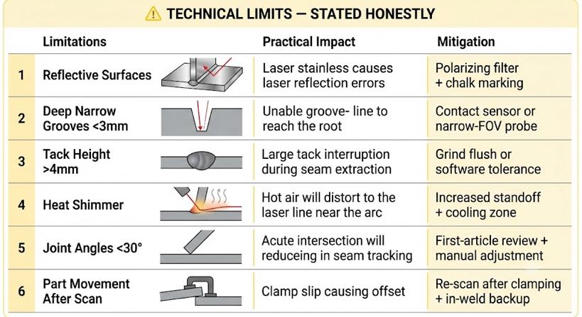
Technical Limits — Stated Honestly
3D laser seam tracking is a mature technology, but it has genuine constraints that any structural steel fabricator should understand before specifying a system.
| Limitation | Practical impact | Mitigation |
| Reflective or transparent surfaces | Highly polished stainless steel can cause specular reflection errors | Reduce scan intensity; use polarising filter; apply chalk marking |
| Very deep narrow grooves (< 3 mm width) | Laser line cannot reach root of deep groove | Use contact sensor or specialised narrow-FOV probe |
| Tack weld height > 4 mm | May interrupt seam extraction if tacks are higher than the gap they bridge | Grind tacks flush or set tack tolerance parameter in software |
| Extreme heat shimmer near arc | Refractive index variation in hot air can distort laser line | Increase torch-to-sensor standoff; use post-arc cooling zone |
| Joint angles < 30° | Acute intersections reduce extraction confidence | First-article path review required; manual adjustment may be needed |
| Part movement after scan | If part shifts after pre-weld scan (e.g., clamp slip), path is offset | Re-scan after final clamping; use in-weld tracking as backup correction |
None of these limitations are disqualifying for standard structural steel work — fillet welds, butt welds, T-joints, and lap joints on common plate thicknesses are all within the technology’s reliable operating envelope. The table above covers edge cases that are worth reviewing against your specific part portfolio before selecting a system.
Frequently Asked Questions
What is the difference between seam tracking and seam finding?
Seam finding (or seam search) locates the joint before welding and adjusts the start point of a pre-programmed path. It corrects for part position but uses a fixed path shape. Seam tracking updates the entire path continuously — both position and geometry — throughout the weld. For structural steel with variable gap and fit-up, tracking is required; seam finding alone does not compensate for gap variation along the joint length.
Does the scanner work through welding fumes and spatter?
Laser triangulation scanners are affected by dense fume columns directly in the beam path. In practice, the pre-weld scan is performed before the arc opens — no fumes present. For in-weld arc tracking, the sensor is typically mounted 80–150 mm ahead of the torch (leading), outside the fume cone. Spatter on the scanner lens is managed with air knife purge systems and replaceable protective glass covers — a standard maintenance item in structural steel environments.
How does the system handle joints that are not straight — curved seams or variable-angle connections?
The point cloud captures the actual three-dimensional geometry of the joint, including curves, angular changes, and compound geometries. The seam extraction algorithm fits a centreline to whatever geometry it finds — straight, curved, or stepped. The path generator then produces the corresponding robot motion, including the torch angle adjustments needed to maintain consistent work angle around curves. Tight-radius curves (< 50 mm) may require path smoothing to avoid robot singularities, which the path planning module handles automatically.
What scan data is stored, and how does it support weld traceability?
Our intelligent welding system logs the point cloud, extracted seam centreline, gap measurements, and generated path data against the part serial number. During welding, arc parameters (voltage, current, travel speed, deviation alerts) are added to the same record. The resulting file provides a complete weld traceability package — geometry plus process parameters per joint — which meets the documentation requirements of AWS D1.1 and EN 1090 for certified structural welding. Records can be exported in standard formats for quality management systems.
Can this technology retrofit onto an existing robotic welding cell?
Laser seam tracking sensors can be added to many existing robot cells as an aftermarket upgrade, provided the robot controller supports the required I/O and update rate. The more complex retrofit is the path planning software — true no-programming path generation from scan data requires software integration at the controller level, not just a sensor addition. For a full evaluation of whether your existing cell can be upgraded vs. replaced, the most reliable approach is a site assessment with the sensor vendor.
Next Steps
- To see how 3D scan data becomes a complete weld program through reverse modelling, read Blog 05: Scan-to-Weld Technology: How Reverse Modeling Replaces Robot Programming.
- To understand how the no-programming cell uses this scanning technology as its foundation, read Blog 03: No-Programming Robotic Welding Cell: How Vision-Guided Systems Eliminate Teach Pendants.
- To request a live scan demonstration on your own structural steel part: send us the part drawing or a photo of the joint configuration. We will run a 3D laser scan and return the extracted seam data, generated path preview, and cycle time estimate.
| Related reading in this series: Blog 01 — Robotic Welding Cell vs Traditional Welding Line: What Changes on Your Shop Floor Blog 02 — Manual vs Robotic Welding for Structural Steel: When Does Automation Pay Off? Blog 03 — No-Programming Robotic Welding Cell: How Vision-Guided Systems Eliminate Teach Pendants Blog 05 — Scan-to-Weld Technology: How Reverse Modeling Replaces Robot Programming |
About the Author
Experience & Credentials
Robotic welding system integration specialist with 12+ years of direct project experience focused on Robot Positioner selection and integration. Has provided consulting to 300+ factories across North America, Europe, and Asia. All specification data in this article is drawn from actual H / B / L / U series product datasheets.
Company background: 26+ years of welding automation engineering, 40+ active patents, 1,500+ completed projects globally, approximately 70% involving Robot Positioner integration.
Certifications
- ISO 9001: 2015 (GB/T 19001-2016) — Quality Management System
- GJB 9001C-2017 — Military/Weapon Equipment Quality Management System
- EU CE — Machinery Directive 2006/42/EC (Cert. No. M.2026.206.C134866)
- High-Tech Enterprise — Cert. No. GR202341000595 (Issued Nov. 2023)
Last updated: Jun 2026
RELATED POSTS
Coordinated Welding Cell: Positioner and Robot as One Kinematic Chain
Can You Trust the Spec Sheet? How to Verify Welding Positioner Accuracy with Laser Trackers and ISO 9283
7th Axis Robot in Welding Automation: Real Case Studies and ROI Examples
Robotic Laser Welding ROI Analysis: Is It Worth the Investment?
ROI of a No-Programming Robotic Welding Cell: A Practical Guide for Structural Steel Applications