Custom Robot Workstations And Laser Systems Manufacturer


Coordinated Welding Cell: Positioner and Robot as One Kinematic Chain
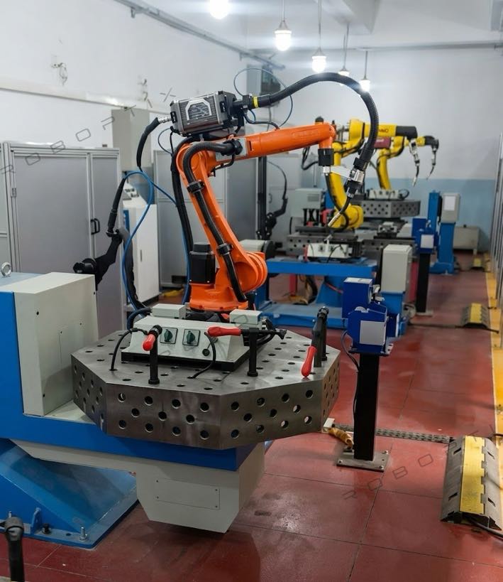
Type “welding positioner for sale” and you will find plenty of standalone machines . But the moment a robot enters the cell, the question shifts from “which positioner” to “how does the positioner move with the robot?” This guide is about that second question. A coordinated welding cell is not two machines bolted together—it is one kinematic chain in which the positioner is an external axis solved by the same controller that drives the robot. We explain why “integration” is the wrong goal, what coordination actually requires, and how ROBOPTIX builds coordinated cells around the 7th Axis Robot Rail System, a Robot Base / Robot Pedestal, and servo positioners .
Why “Integration” Is the Wrong Goal
Most buyers ask suppliers to “integrate” a positioner with a robot. Integration implies two independent controllers exchanging handshakes: the robot finishes a move, signals done, the positioner rotates, signals back, the robot resumes. That stop-start handshake is exactly what ruins a weld. Coordination is different. In a coordinated cell the positioner is declared as axis 7, 8, or 9 inside the robot controller, and a single inverse-kinematics solve drives every axis—robot and positioner—along one trajectory . You stop integrating and start solving. The distinction decides whether your seam is welded at a constant speed or in a series of jerks.
One Kinematic Chain: The Positioner as an Extension of the Robot
A robot arm has six axes; a coordinated positioner adds more. A Headstock Tailstock Positioner contributes one rotate axis, a Horizontal 3-Axis Rotary Positioner can add two or three. Once the controller knows the positioner’s geometry, the weld path is planned in Cartesian space and the controller computes the joint angles for the robot and the angles for the positioner simultaneously . The operator teaches one path, not two programs. This is also where type selection still matters: the family you pick decides which axes exist to be coordinated.
What Coordination Actually Requires
Three hard problems separate a coordinated cell from a merely decorated one.
External-Axis Interpolation
The controller must interpolate the positioner’s rotation or tilt as part of the weld path, not as a separate move queued after the robot. Without external-axis interpolation, the TCP speed is the robot’s speed alone, and the positioner only catches up between welds—fine for tacking, fatal for a continuous seam. With it, the combined TCP speed stays inside the process window for the whole pass.
Calibrating the Positioner Frame to the Robot Base
The positioner’s work envelope has to be expressed in the robot’s base frame, and a Robot Base / Robot Pedestal is what makes that frame stable and repeatable . A frame calibration error of just 1 mm at a 500 mm tool offset rotates the TCP by about 0.11°, shifting the seam by roughly 1 mm—outside a ±0.5 mm tolerance before a single weld is laid. ROBOPTIX calibrates the positioner frame to the robot base during commissioning and re-verifies it with a laser tracker .
Synchronization
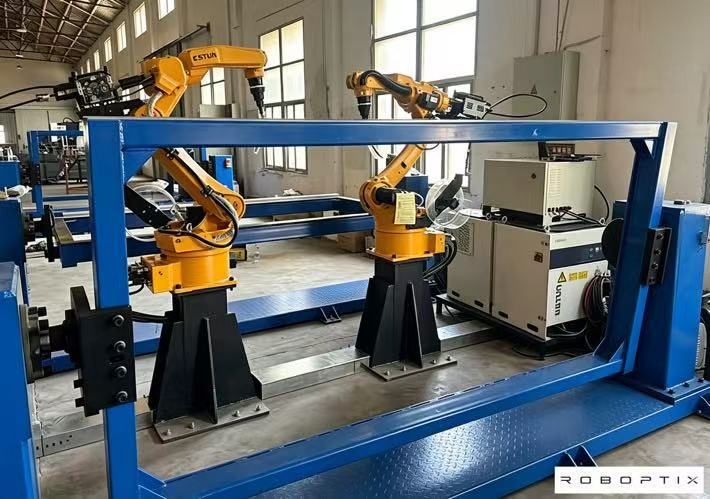
Even with correct frames, the axes must move at the same instant. ROBOPTIX coordinated cells use EtherCAT distributed clocks so the robot and positioner share a jitter-free time base; a few milliseconds of lag shows up as TCP speed variation and, on a pulsed process, as visible ripples in the bead. Synchronization is not a feature you toggle—it is the floor the whole cell stands on.
Constant TCP Speed Through the Weld
Weld quality lives or dies on heat input, and heat input lives or dies on TCP speed. When the robot and positioner are coordinated, the controller holds the combined TCP speed constant through corners and contour changes . When they are not, the speed spikes wherever the robot alone has to compensate, and the pool overheats or starves. For a 1.2 mm mild-steel fillet at 1000 mm/min, a 20% speed dip cuts penetration by roughly 15%—the kind of variation that fails a weld procedure qualification. The hidden specs that decide this—backlash, stiffness, thermal drift—are exactly why they matter here too .
Path Smoothing and Blended Motion
Coordination also enables corner blending and look-ahead: the controller plans beyond the current point and rounds the transition so the TCP never stops. On a rectangular frame welded in one mount (L-Type Welding Positioner), blended motion turns four separate welds into one continuous pass—fewer starts, fewer defects, and no operator re-fixturing between sides.
The Gravity Constant: How Coordination Protects Weld Quality
Gravity is not a neutral background force; it decides whether your molten pool sits flat or fights you. A coordinated Horizontal 3-Axis Rotary Positioner can keep even a complex contour in the flat (1G) position while the robot welds, so gravity stabilizes the pool instead of distorting it . That is the physical reason coordination pays off on multi-orientation work—not just cycle time.
ROBOPTIX Coordinated-Cell Building Blocks
A coordinated cell is an assembly, not a single SKU. ROBOPTIX pairs the robot with a 7th Axis Robot Rail System that extends reach, a Robot Base / Robot Pedestal that defines the stable base frame, and servo positioners—Headstock Tailstock Positioner, L-Type Welding Positioner, U-Type Welding Positioner, Horizontal 3-Axis Rotary Positioner, Vertical Tilting Positioner, or Single Axis Rotary Positioner—declared as external axes. For shops without robot programmers, the same cell ships as a no-programming vision-guided unit; for a faster start, as a turnkey workstation; and for laser processes, on a laser-ready platform. Non-standard geometries are handled by the custom program.
Worked Examples
Structural-Steel I-Beam (robot + L-Type Welding Positioner)
A fabricator running roughly 200 I-beams per week replaced two robots and manual flips with one robot plus an L-Type Welding Positioner coordinated as external axes. The beam is presented flat on every face in one mount, and blended motion welds it in a single pass. Crane cycles dropped about 60% and re-fixturing time effectively to zero . The coordination is what made the single-pass weld geometrically possible.
Pressure-Vessel Shell (robot + Headstock Tailstock Positioner)
A vessel shell needs a circumferential seam welded while it rotates. The robot welds; the Headstock Tailstock Positioner rotates as a coordinated external axis so the seam stays in the flat position at constant TCP speed. No turning rolls—the shell spins between driven and idler centers. The cell holds the tolerance the procedure qualification demands because the speed never spikes.
Mixed-Geometry Casting (robot + Horizontal 3-Axis Rotary Positioner)
A casting with seams on faces no single flip reaches is oriented joint-by-joint by a Horizontal 3-Axis Rotary Positioner while the robot follows, each seam kept flat. No simpler family can do this coordinated; specifying a single-axis unit would leave welds the robot cannot reach .
Your Coordinated-Cell Specification Checklist
Send these inputs and ROBOPTIX returns a coordinated specification before you buy—no paywall hiding the math.
| Input | What to specify | Why it decides coordination |
| Robot make & controller | Brand, controller family, external-axis licenses | Sets whether the positioner can be declared as axis 7–9 at all |
| Positioner family & axes | From type selection : Headstock, L-Type, 3-Axis… | Decides which external axes exist to coordinate |
| External-axis protocol | EtherCAT / Profinet / Modbus | Determines sync quality and jitter |
| Required TCP speed window | mm/min range your process tolerates | Drives servo grade and interpolation need |
| Tolerance band | Pose accuracy AP / repeatability RP (ISO 9283:1998) | Decides calibration + laser-tracker verification |
| Throughput target | Parts/hour, handling time budget | Flags where 7th Axis Robot Rail System removes crane cycles |
When a Coordinated Cell Isn’t the Answer
A coordinated cell is not always the right buy. For low-volume work, loose tolerances (±1 mm), or parts an operator can flip by hand, a standalone positioner plus manual welding—or the fixture-free approach—wins on total cost. Audit any supplier before committing , and weigh the five-year total cost of ownership against the sticker; a coordinated cell you only half-use is the expensive machine. Spend on coordination where the part justifies it; skip it where it does not. Judgment, not ritual, protects the budget.
Frequently Asked Questions
Q: What is the difference between integrating and coordinating a positioner with a robot?
A: Integration links two controllers that handshake; coordination declares the positioner as an external axis in the robot controller so one kinematic solve drives both. Coordination holds constant TCP speed; integration stitches moves together with stops.
Q: Do I need a servo positioner to coordinate?
A: Yes. External-axis interpolation requires a servo positioner the controller can command continuously—Headstock Tailstock Positioner, L-Type Welding Positioner, U-Type Welding Positioner, Horizontal 3-Axis Rotary Positioner, Vertical Tilting Positioner, or Single Axis Rotary Positioner. ROBOPTIX never uses idle turning rolls, which cannot be coordinated at all.
Q: Which positioner family works best as an external axis?
A: It follows your part geometry : long rotational work → Headstock Tailstock Positioner;
multi-face beams → L-Type Welding Positioner;
large irregular → U-Type Welding Positioner;
mixed complex seams → Horizontal 3-Axis Rotary Positioner;
heavy plate both sides → Vertical Tilting Positioner.
The family decides the axes; coordination decides how smoothly they move with the robot.
Q: How is coordinated-cell accuracy verified?
A: ROBOPTIX is ISO 9001-certified and reports pose accuracy AP and pose repeatability RP per ISO 9283:1998, with load, temperature, and speed stated, and supports third-party or on-site laser-tracker verification . The conditions are the number; a repeatability figure without them is a half-truth.
Q: Can a 7th Axis Robot Rail System be part of the coordinated cell?
A: Yes. The 7th Axis Robot Rail System extends the robot’s linear reach as another coordinated axis, and the Robot Base / Robot Pedestal gives the whole cell a stable frame . Together they let one robot serve a long part without repositioning.
A coordinated welding cell is one kinematic chain, not two machines that learned to shake hands. Treat the positioner as an external axis—servo, frame-calibrated, and synchronized—and the robot and positioner weld as one, at constant TCP speed, with gravity working for you. ROBOPTIX is ISO 9001-certified, builds the cell from the 7th Axis Robot Rail System, Robot Base / Robot Pedestal, and servo positioners, and reports accuracy per ISO 9283:1998. Send us your robot model, part drawing, and tolerance band and we will spec the coordinated cell—before you buy, not after.
Not sure whether your part needs coordination?
Send ROBOPTIX your robot model and part drawing for a free coordinated-cell specification.
About the Author
Experience & Credentials
Robotic welding system integration specialist with 12+ years of direct project experience focused on Robot Positioner selection and integration. Has provided consulting to 300+ factories across North America, Europe, and Asia. All specification data in this article is drawn from actual H / B / L / U series product datasheets.
Company background: 26+ years of welding automation engineering, 40+ active patents, 1,500+ completed projects globally, approximately 70% involving Robot Positioner integration.
Certifications
High-Tech Enterprise — Cert. No. GR202341000595 (Issued Nov. 2023)
ISO 9001: 2015 (GB/T 19001-2016) — Quality Management System
GJB 9001C-2017 — Military/Weapon Equipment Quality Management System
EU CE — Machinery Directive 2006/42/EC (Cert. No. M.2026.206.C134866)
References
[1] International Organization for Standardization. (1998). ISO 9283:1998, Manipulating Industrial Robots — Performance Criteria and Related Test Methods.
[2] Park, J.-H., Kim, S.-H., Moon, H.-S., & Kim, M.-H. (2019). Influence of Gravity on Molten Pool Behavior and Analysis of Microstructure on Various Welding Positions in Pulsed Gas Metal Arc Welding. Applied Sciences, 9(21).
[3] Liu, J., Jiang, F., Chen, S., Xu, B., Zhang, G., Cheng, W., & Ma, X. (2023). Mechanisms of Gravitational Influence on Weld Pool Behavior and Weld Bead Performance in Variable Polarity Plasma Arc Welding across Different Welding Position. Materials, 16(19).
RELATED POSTS
How to Install and Integrate a 7th Axis Robot: Step-by-Step Guide & Best Practices
Can You Trust the Spec Sheet? How to Verify Welding Positioner Accuracy with Laser Trackers and ISO 9283
Welding Positioner Types Compared: Headstock, L-Type, U-Type, 3-Axis & More
Laser Welding Positioner: Accuracy and Speed for Thin-Gauge Welds
No-Programming Robotic Welding Cell: Vision-Guided, No Teach Pendant