Custom Robot Workstations And Laser Systems Manufacturer


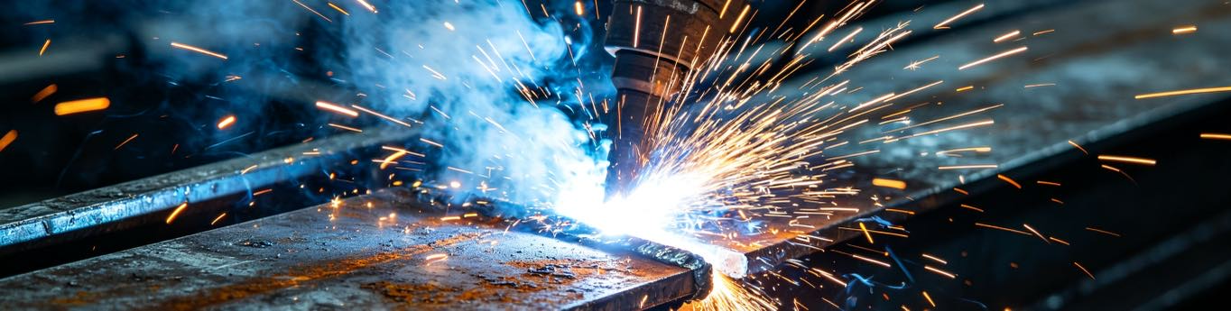
No-Programming Robotic Welding Cell: Vision-Guided, No Teach Pendant
You searched “welding positioner for sale” and found machines. But the real blocker on most shop floors is not the hardware—it is the robot programmer you do not have. A No-Programming Robotic Welding Cell removes that blocker: a camera sees the part, software generates the weld path, and the robot and positioner run it with no teach pendant and no offline programming. This guide explains how vision-guided cells work, where their accuracy actually comes from, which parts they fit, and—honestly—where they still fall short. If you have not chosen a positioner family yet, start with type selection; for the full family comparison, see the six-family table.

The Bottleneck Isn’t the Robot—It’s the Programmer
A conventional robotic Welding Robot Cell needs a skilled programmer to jog the robot, teach every point on a pendant, and tune the path for each new part. At ~4–8 hours of teach time per new batch, programming—not welding—becomes the slow, expensive step. Shops without that skill either pay an integrator for every drawing change or never automate at all. The No-Programming Robotic Welding Cell exists precisely for that shop: it trades the programmer for a camera and an algorithm.
What “No Programming” Actually Means
It does not mean “dumber.” It means the path is derived, not taught. The operator loads the part on a positioner—often an L-Type Welding Positioner or a Single Axis Rotary Positioner—and the system handles the rest. No pendant, no code, no offline simulation license. ROBOPTIX still builds the cell from the same coordinated building blocks, so “no programming” is a usability layer on top of a real external-axis cell, not a toy. The positioner can later be declared as an external axis and coordinated exactly like any other.
How a Vision-Guided Cell Works
Three steps replace the programmer.
Part Localization—the Camera Sees the Part
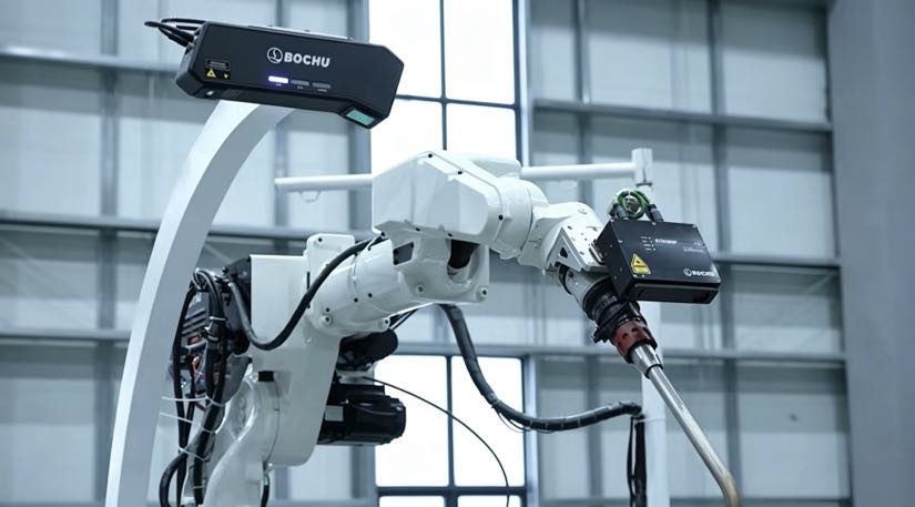
A 3D or structured-light camera scans the loaded part and locates it in space—within the robot’s frame—without any fixturing or datum marks. This is what makes the cell fixture-free: the part can land anywhere in the work envelope. Localization accuracy is the foundation everything else builds on, so ROBOPTIX calibrates the camera to the robot base frame during commissioning.
Automatic Path Generation
Software matches the scanned geometry to a weld-feature model and generates the seam path: start, weave, parameters. The operator approves or nudges it; they do not draw it point by point. Because the path is generated in Cartesian space, the controller can then plan it through the positioner as one kinematic chain—the same coordinated motion a programmed cell uses, just sourced differently.
Coordinated Execution
The robot and a servo positioner (declared as an external axis) weld at constant TCP speed while the positioner keeps the seam in the flat (1G) position. Gravity stabilizes the puddle instead of fighting it . No turning rolls—the part is held on a rotary table, tilt axis, or between driven centers, all servo-controlled and coordinate with the robot.
The Math: Where the Accuracy Comes From
A No-Programming Cell lives or dies on camera calibration, not on the robot. The weld path error the part sees is the root-sum-square of the two dominant sources: vision localization and positioner repeatability. With a vision system localizing within ±0.5 mm and a ROBOPTIX servo positioner holding pose repeatability RP of ±0.05 mm per ISO 9283:1998, the combined path error is √(0.5² + 0.05²) ≈ ±0.50 mm. Vision dominates, so we state the localization condition just as strictly as the robot condition: a “no-programming” claim without a stated localization tolerance is the same half-truth as a repeatability number without load and speed. ROBOPTIX supports laser-tracker verification of the whole chain.
Which Parts a No-Programming Cell Fits
Match the family to your part geometry first : round and rotational parts suit a Single Axis Rotary Positioner; beams, boxes, and multi-face work suit an L-Type Welding Positioner; large irregular frames suit a U-Type Welding Positioner. The no-programming layer adds the most value where batches change often and volumes are moderate—every new drawing used to mean a programmer, now it means a camera scan. For long, single-orientation rotational seams, a Headstock Tailstock Positioner coordinated to the robot is often simpler and just as hands-off . Let geometry, not marketing, drive the choice.
Worked Example
Mixed-Bracket Job Shop (robot + L-Type Welding Positioner)
A job shop welding roughly 300 mixed brackets per week used to pay an integrator 4–8 hours of teach-pendant programming for every new batch. After switching to a No-Programming Robotic Welding Cell built around an L-Type Welding Positioner, the camera localized and pathed each bracket in under 90 seconds. First-article setup dropped about 95%, re-fixturing between sides disappeared because the positioner presented every face flat, and the shop stopped paying for a programmer on every drawing change. The coordination is what made the hands-off weld geometrically possible.
No-Programming vs Coordinated vs Turnkey
| Approach | Needs robot programmers? | Best for | ROBOPTIX link |
| No-Programming (vision) | No | High-mix, moderate-tolerance, frequent changes | This page |
| Coordinated cell | Yes (once) | High-volume, tight tolerance, complex motion | Coordinated cell |
| Turnkey workstation | No | Faster start, fixed repeatable part | Turnkey |
When a No-Programming Cell Isn’t the Answer
Vision-guided is not universal. For very tight tolerances (±0.1 mm class), highly reflective or translucent parts that fool a camera, or exotic joint geometries the feature model cannot recognize, a programmed coordinated cell with a skilled operator wins . Audit any supplier before committing—a factory visit and bench test beat a spec-sheet promise —and weigh five-year total cost of ownership against the sticker. A No-Programming Cell you only run on three part numbers is the expensive convenience. Spend on it where the mix justifies it; skip it where it does not.
When NOT to choose it
If your parts are a stable, high-volume family, a turnkey workstation is cheaper to run and easier to lock down. If tolerances are tight and surfaces are camera-hostile, a programmed coordinated cell is the honest choice. Judgment, not ritual, protects the budget.
ROBOPTIX Builds the No-Programming Robotic Welding Cell
ROBOPTIX pairs the vision system with the same coordinated building blocks: a 7th Axis Robot Rail System that extends reach , a Robot Base / Robot Pedestal that defines the stable base frame, and servo positioners—Headstock Tailstock Positioner, L-Type Welding Positioner, U-Type Welding Positioner, Horizontal 3-Axis Rotary Positioner, Vertical Tilting Positioner, or Single Axis Rotary Positioner—declared as external axes. For a fixed part, the same hardware ships as a turnkey workstation; for laser processes, on a laser-ready platform; and for non-standard geometries, through the custom program. The No-Programming Robotic Welding Cell is one configuration of a Welding Robot Cell—not a separate, weaker machine.

Frequently Asked Questions
Q: Do I really need no robot programming experience?
A: For daily operation, no. You load the part and approve the auto-generated path; you do not teach points on a pendant. Initial commissioning and any exotic part still benefit from ROBOPTIX engineering support.
Q: How accurate is a no-programming vision cell?
A: Path error is the root-sum-square of vision localization (±0.5 mm typical) and positioner repeatability RP (±0.05 mm per ISO 9283:1998), about ±0.50 mm combined. Accuracy depends on camera calibration stated under real conditions —not on a bare claim.
Q: Which positioner family works with it?
A: Any servo family matches your geometry: Single Axis Rotary for round parts, L-Type for beams/boxes, U-Type for large irregular frames, Headstock Tailstock for long rotational seams, 3-Axis for complex mixed seams, Vertical Tilting for heavy plate.
Q: Is it the same as a coordinated welding cell?
A: It uses the same coordinated external-axis motion; “no-programming” is a vision usability layer on top, not a different machine. The path is derived by camera instead of taught by a programmer.
Q: When should I NOT buy a no-programming cell?
A: For ±0.1 mm-class tolerance, camera-hostile reflective/translucent surfaces, or joint geometries the model cannot recognize, choose a programmed coordinated cell. For a stable high-volume family, a turnkey workstation runs cheaper. Audit the supplier first.
A No-Programming Robotic Welding Cell trades the robot programmer for a camera and an algorithm—loading the part is the only skill required. Its accuracy comes from camera calibration and a coordinated servo positioner holding RP per ISO 9283:1998, not from a weaker machine. ROBOPTIX is ISO 9001-certified, builds the cell from the 7th Axis Robot Rail System, Robot Base / Robot Pedestal, and servo positioners, and supports laser-tracker verification.
About the Author
Experience & Credentials
Robotic welding system integration specialist with 12+ years of direct project experience focused on Robot Positioner selection and integration. Has provided consulting to 300+ factories across North America, Europe, and Asia. All specification data in this article is drawn from actual H / B / L / U series product datasheets.
Company background: 26+ years of welding automation engineering, 40+ active patents, 1,500+ completed projects globally, approximately 70% involving Robot Positioner integration.
Certifications
High-Tech Enterprise — Cert. No. GR202341000595 (Issued Nov. 2023)
ISO 9001: 2015 (GB/T 19001-2016) — Quality Management System
GJB 9001C-2017 — Military/Weapon Equipment Quality Management System
EU CE — Machinery Directive 2006/42/EC (Cert. No. M.2026.206.C134866)
References
[1] International Organization for Standardization. (1998). ISO 9283:1998, Manipulating Industrial Robots — Performance Criteria and Related Test Methods.
[2] Park, J.-H., Kim, S.-H., Moon, H.-S., & Kim, M.-H. (2019). Influence of Gravity on Molten Pool Behavior and Analysis of Microstructure on Various Welding Positions in Pulsed Gas Metal Arc Welding. Applied Sciences, 9(21), 4626.
[3] Liu, J., Jiang, F., Chen, S., Xu, B., Zhang, G., Cheng, W., & Ma, X. (2023). Mechanisms of Gravitational Influence on Weld Pool Behavior and Weld Bead Performance in Variable Polarity Plasma Arc Welding across Different Welding Position. Materials, 16(19), 6457.
RELATED POSTS
How to Integrate a Vision-Guided Robotic Welding cell into an Existing Fabrication Line

Robotic Welding Cell vs Manual Welding: Which Is Better for Modern Manufacturing?
How to Select a Robotic Laser Welding Supplier: From Technical Assessment to Sample Testing
What Is a Robotic Welding Cell? 2026 Beginner’s Guide | 37 Shop Data
How a Welding Positioner Controls Gravity: The Physics of Puddle Stability and Weld Quality