Custom Robot Workstations And Laser Systems Manufacturer


Can You Trust the Spec Sheet? How to Verify Welding Positioner Accuracy with Laser Trackers and ISO 9283
Every welding positioner catalog leads with a repeatability number: ±0.03 mm, ±0.05 mm, occasionally ±0.01 mm for high-end servo units. For an international buyer comparing quotes across suppliers and continents, that digit becomes the scoreboard—lower looks better, and the purchase decision often follows it. The uncomfortable truth the spec sheet hides is that the number was earned in a laboratory, under a narrow set of conditions your factory will never reproduce. Trust it blindly and you can discover, weeks after installation and commissioning, that the welding positioner which “tested perfect” cannot hold your part where the robot expects it. The cost of that discovery is not just rework; it is a stalled line, a missed shipment, and a credibility hit with your own customer.
This article explains how to verify welding positioner accuracy the way a professional buyer or engineer should: with a laser tracker, against the ISO 9283 framework, and with clear eyes for the gap between factory inspection and field acceptance. We go past the headline number into what it means, how it is—and is not—measured, and how to write the verification requirement into your purchase order so the claim becomes a contract, not a hope. The goal is not to distrust every supplier; it is to replace trust with measurement.
Note: The welding positioner verification methodology here reflects ROBOPTIX acceptance practice across servo-driven cells and aligns with ISO 9283:1998 (Manipulating industrial robots—Performance criteria and related test methods).
The weld-quality linkage is cross-referenced with peer-reviewed position-dependent pool-behavior research (Park et al., 2019; Liu et al., 2023).
1. The Spec Sheet Promise
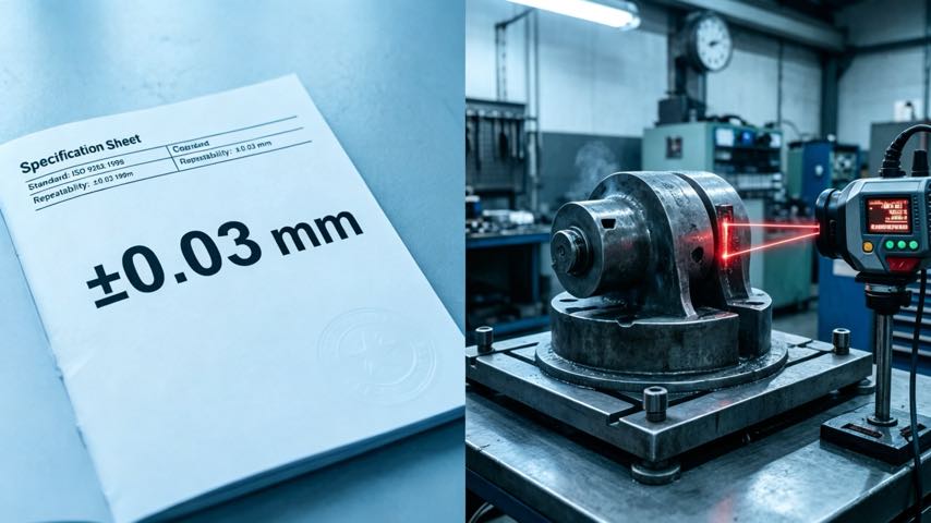
Repeatability is the most quoted and least understood number on a welding positioner data sheet. It sounds like a guarantee: “this axis will return to the same place within ±0.03 mm, every time.” In a narrow, literal sense it is true—at the supplier’s factory, at a single controlled temperature, with no load on the faceplate, moving slowly between measurements. The problem is not that the claim is false. It is that the claim is a single test point, earned under ideal conditions, dressed up as a general promise about your production floor. International buyers comparing two quotes often fixate on this one digit while ignoring the conditions attached to it—and those conditions are exactly where real performance lives or dies.
Consider what the number is competing against in your mind. A supplier quoting ±0.03 mm looks “better” than one quoting ±0.05 mm, so they win the comparison—even if the first measured at 20 °C unloaded and the second measured at temperature with the actual part mounted. The spec sheet is silent on that context. Your job as the buyer is to make the context explicit before you sign, because the context is the difference between a number you can weld with and a number you cannot.
2. What the Number Actually Measures (and What It Doesn’t)
Before you can verify a welding positioner, you have to know what its headline number does and does not describe. The two words most often confused are repeatability and accuracy, and the confusion is expensive.
2.1 Repeatability vs Accuracy
- Repeatability: How tightly the axis returns to the same commanded pose over many repeated cycles. It is a statement about consistency, not correctness. An axis can be exquisitely repeatable and still be systematically wrong.
- Accuracy: How close the achieved pose is to the commanded pose. An axis can be perfectly repeatable yet offset from truth by 0.5 mm—repeatable-true, accurate-false. That constant offset is usually fixable with frame calibration; what it is not is a defect in the hardware.
Here is the worked picture. Suppose a tilt axis is commanded to 45° and, over ten repetitions, lands at 45.00°, 45.01°, 44.99°, 45.00°… a spread of roughly ±0.02 mm at the measurement radius. That is excellent repeatability. But suppose its mean is actually 44.6°—it is consistently 0.4° off. That is poor accuracy. For welding, repeatability matters most for day-to-day consistency; accuracy matters the moment you teach a program in the robot frame or expect two cells to make identical parts. The spec sheet quotes repeatability for a reason: it is the flattering number, and it says nothing about the offset.
2.2 What Repeatability Does NOT Capture
Just as important is what the headline repeatability leaves out. It typically excludes load (the axis is empty during the test), thermal state (cold start, not after hours of operation), dynamic motion (slow creep, not production acceleration), and the contribution of backlash and elastic deformation in the drive chain—the hidden specs from Backlash, Stiffness & Thermal Drift: The Hidden Welding Positioner Specs. A welding positioner that repeats beautifully empty at 20 °C can still drift under a hot, heavy, fast-cycling part. Repeatability is necessary but far from sufficient; treat it as one input to a larger judgment, never the whole judgment.
3. ISO 9283: The Standard That Should Govern the Claim
ISO 9283:1998 defines how the performance of manipulating industrial robots—and, by direct extension, rotating and tilting positioners—should be measured. It is the internationally recognized yardstick, which makes it the right reference point when suppliers from different countries quote different numbers. The standard specifies a family of performance characteristics: pose accuracy (AP), pose repeatability (RP), path accuracy (AT), path repeatability (RT), drift of pose accuracy during constant operation, overshoot, settling (stabilization) time, and static compliance. For a welding positioner, the two that matter most are pose repeatability RP and, when the axis moves during welding (as in coordinated motion), path repeatability RT.
Equally important is how ISO 9283 says to measure. It prescribes a set of defined test poses distributed through the working envelope, a specified number of repetitions at each, and a statistical treatment—typically the spread contained within a ±2σ or ±3σ band. A repeatability claim that does not state which standard, which poses, which repetitions, which temperature, and which confidence band it used is, professionally speaking, an opinion rather than a measurement. The smaller the σ band, the tighter the claim—and ±3σ is roughly 50% wider than ±2σ for the same data, so the two are not interchangeable.
3.1 A Worked Look at the Numbers
Imagine a supplier reports “repeatability ±0.05 mm” with no other detail. Ask for the ISO 9283 report and you might find: poses at 0°, 45°, 90°, 135°, 180° tilt, ten repetitions each, at 20 °C unloaded, reported at ±2σ. That is a legitimate, if optimistic, number. Now ask for the same grid with the 1.5-ton production part mounted and the cell at 30 °C after two hours of running. The same axis may report ±0.12 mm. Both are “true”—they are just different tests. The report, not the headline, is what you buy against, and the report is where the real comparison between suppliers finally becomes fair.
4. Laser Tracker Verification: How to Actually Measure It
A laser tracker is a portable coordinate-measuring device built around a tightly controlled laser beam. It fires the beam at a spherically mounted retroreflector (SMR)—a small ball-mounted mirror—and determines the target’s 3D position from the measured angles and the absolute distance to the target (an interferometer for incremental distance, an absolute distance meter for the initial lock). Mount an SMR on the welding positioner faceplate or chuck, command the axis through a set of angles, and the tracker records where the target actually went in space. You are now measuring the welding positioner the way your robot will experience it—in real coordinates, with real geometry—rather than as a number on a bench report.
The trick that makes this powerful is geometric amplification. A small angular error at the axis becomes a large linear error at the tip of an offset target. If your SMR sits 500 mm from the rotation center and the axis is off by 0.05°, the target moves about 0.44 mm—roughly nine times easier for the tracker to resolve than the angular error itself. Mount the target as far out on the faceplate as practical and the welding positioner’s tiny angular mistakes become comfortably measurable. This is why a laser tracker, not a dial indicator, is the right tool for verifying a precision positioner, and why the measurement is both fast and defensible in a dispute.
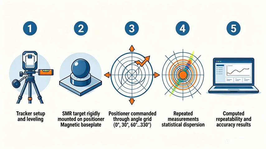
4.1 A Practical Laser Tracker Procedure
- 1. Setup and level: Place the tracker so it has a clear line of sight across the full rotation or tilt arc; level the welding positioner and let it thermally stabilize—at least 30 minutes after power-up, because the first cycles run cold and the frame is still settling. Record ambient and positioner-surface temperature.
- 2. Mount the target rigidly: Fix the SMR to the faceplate at a known, preferably large radius. Rigidity matters: any movement of the target relative to the faceplate is measured as positioner error and corrupts the result. Use a magnetic or bonded nest, never a hand-held target.
- 3. Command a pose grid: Drive the axis through a representative set of commanded angles—for a rotate axis, 0°, 30°, 60° … 330°; for a tilt axis, a similar sweep across its working range. At each pose, take multiple (ideally ten) repeated measurements with the axis re-commanded each time, so you capture repeatability, not a single lucky reading.
- 4. Compute repeatability (RP): For each commanded angle, take the spread of the repeated readings and report the maximum spread and the ISO 9283 RP figure (the ±2σ or ±3σ radius). This is your real, field-verified welding positioner repeatability.
- 5. Compute accuracy (AP) and convert to angle: Compare the mean achieved position at each pose to the commanded position; the maximum deviation is pose accuracy. Convert the linear deviation at the known target radius back to an angular error so you can compare it directly to the supplier’s angular spec. Document temperature and load at every step.
4.2 From Linear Deviation to Angular Error
Suppose at a commanded 90° tilt, your SMR at a 400 mm radius lands 0.30 mm below its commanded position, mean over ten reads. The angular error is roughly arctan(0.30 / 400) ≈ 0.043°. If the welding positioner was quoted at ±0.03° tilt accuracy, you have now independently confirmed it is marginally outside spec—or, if the part was mounted and warm, you have quantified exactly how much the field condition costs you. Either way you are negotiating from measurement, not faith, and you can decide whether the gap matters for your weld tolerance.
5. The Factory-vs-Field Gap
The number you verify at the supplier’s bench is not the number you will get on your floor. The table below names the dimensions of that gap and, crucially, what to do about each.
| Dimension | Factory test | Field reality | Mitigation |
| Temperature | Controlled 20 °C | Shop swings 15–35 °C; thermal growth shifts frames | Warm up before qualifying; re-measure at operating temp |
| Load | Unloaded or light test mass | Real part weight induces sag and backlash (P04, P05) | Verify with the actual part or representative mass |
| Speed | Slow, gentle indexing | Production acceleration spikes dynamic error | Test at or near production cycle speed |
| Cables / hoses | Neat, well supported | Dress-pack drag loads the axis | Measure with dress pack installed |
| Foundation | Precision-mounted, leveled | Floor not perfectly rigid or level | Level and shim at install; re-verify after anchoring |
| Duration | Short burst of cycles | Hours of operation → drift (ISO 9283 drift) | Run a drift test; check after 2–4 h |
None of these is cheating by the supplier. They are simply not your conditions. The professional move is to write the field conditions into the acceptance test so the gap is measured, not discovered after commissioning.
6. Writing the Accuracy Clause Into Your Purchase Order
This is where international buyers protect themselves, and it is the step most consistently skipped. A vague “±0.05 mm repeatability” in a quote becomes a vague, unenforceable promise. Turn it into a clause: “Welding positioner pose repeatability RP ≤ 0.05 mm and pose accuracy AP ≤ 0.10 mm, per ISO 9283:1998, measured at 25 °C with the [named] production part mounted at [mass] kg, at [speed] °/s, reported at ±2σ, using a laser tracker.” Now the claim is a specification with a method, a condition, and a measurement tool. If the supplier cannot meet it at your part and temperature, you learn that before shipping, not after. ROBOPTIX supplies welding positioners with ISO 9283-referenced reports and supports writing—and meeting—exactly this kind of clause, because a number you can enforce is worth more than a number you can only admire.
7. Five Questions to Ask Before You Trust the Number
- Which standard? ISO 9283 or another? Unspecified equals unverifiable, and you should treat it as marketing rather than measurement.
- Which poses and repetitions? A single angle tested ten times is not the full working envelope. Demand a grid across the range you actually use, not the one that flatters the axis.
- At what load and temperature? Unloaded 20 °C numbers hide the field error that bites you. Insist on your part, at your temperature, under your duty cycle.
- What confidence band? ±2σ and ±3σ differ by roughly 50%; know which you were quoted, because the wider band makes any number look better than it is.
- Do you have the test report? A claim without the raw report—poses, repetitions, temperature, σ band—is a claim, not evidence. Ask for the document, not the bullet point.
8. Field Example: The ±0.05 mm That Wasn’t
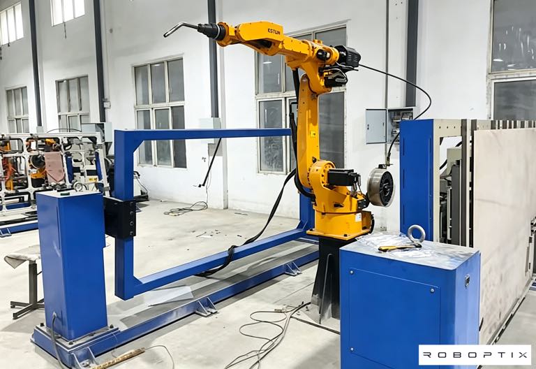
A ROBOPTIX customer received a welding positioner quoted at ±0.05 mm repeatability, backed by the supplier’s factory report under ISO 9283 at 20 °C unloaded. On the floor, with a 1.5-ton part and a 30 °C shop, seam tracking wandered by up to 0.4 mm at the far end of the part—roughly eight times the quoted figure. We re-ran the laser-tracker grid with the part mounted and logged temperature: the axis itself repeated within ±0.06 mm, essentially as quoted, but load-induced sag and thermal drift had shifted the mean by 0.35 mm. After shimming the foundation, adding a thermal warm-up routine, and re-calibrating the robot frame to the positioner, field repeatability settled to ±0.08 mm—acceptable for the weld, and honest about what the cell could actually do. The axis was never “bad”; the spec was simply a different world, and the laser tracker was what translated between the two.
9. When the Spec Sheet Is Good Enough
For many applications, the catalog repeatability is perfectly adequate, and chasing ISO 9283 verification with a laser tracker is over-engineering that costs time and money for no return. If your weld tolerance is ±1 mm or looser, if the part is small and the shop temperature stable, and if you re-calibrate the frame at install, the spec-sheet number will hold in practice and a verification day would confirm what you already knew. Verification earns its cost when tolerances tighten (±0.2 mm and below), when parts are large or heavy, or when first-pass yield is already marginal and you cannot afford a hidden offset. Spend the laser-tracker day where the tolerance lives; skip it where a tape measure and a calibration would do. The point is judgment, not ritual—and judgment is what separates a buyer who specifies from one who merely hopes.
Frequently Asked Questions
Q: What does ±0.03 mm repeatability actually mean on a welding positioner?
A: It means the axis returns to the same commanded pose within a 0.03 mm spread under the supplier’s test conditions—typically unloaded, at a controlled temperature, moving slowly. It is a best-case laboratory figure about consistency, not a guarantee of accuracy or of performance under your loaded, warm, fast-cycling shop floor.
Q: How do I verify welding positioner accuracy with a laser tracker?
A: Mount a retroreflector target on the faceplate at a known radius, command the axis through a grid of angles, and record the achieved 3D positions at each, with several repeated readings per pose. The spread of repeats gives repeatability; the offset from commanded gives accuracy. Convert the linear deviation at the target radius back to an angle to compare with the spec. Ideally repeat the grid with the real production part mounted and at operating temperature.
Q: Is ISO 9283 the right standard for welding positioners?
A: ISO 9283:1998 defines pose accuracy, pose repeatability, path accuracy, and drift for manipulating robots, and is the accepted international framework for rotating and tilting positioners too. Ask for the actual test report—poses, repetitions, temperature, and the σ confidence band—not just the headline number, because the conditions determine what the number means.
Q: Why is factory-measured accuracy better than field accuracy?
A: Factory tests run unloaded at controlled temperature and slow speed on a leveled, rigid mount. The field adds part weight (sag and backlash), thermal growth, cable drag, and hours of operation that induce drift per ISO 9283. Re-verifying under load and at temperature—and writing those conditions into the purchase order—closes most of that gap before you commit.
The repeatability number on a welding positioner spec sheet is real, but it is a laboratory number—earned unloaded, at 20 °C, moving gently. Trusting it as your field performance is the most common and most expensive mistake in positioner buying, because the conditions attached to it are never your conditions. The fix is not cynicism; it is measurement, made enforceable. Adopt the ISO 9283 framework, run a laser-tracker grid with the real part mounted and at temperature, convert the readings back to angles, and—decisively—write the result into your purchase order as a clause with a method, a condition, and a tool. Then the number you buy on is the number you weld with.
ROBOPTIX supplies welding positioners with ISO 9283-referenced repeatability reports and supports on-site laser-tracker acceptance, including loaded and at-temperature verification and purchase-order clause drafting, so the specification is a contract rather than a hope. For most heavy or tight-tolerance work, that verification day pays for itself the first time it prevents a misaligned seam or a rejected shipment. The next article (P08) shifts from verifying the machine to matching it to your part: round, rectangular, and irregular workpieces, and the welding positioner configuration each demands.
Ask ROBOPTIX for an ISO 9283-referenced report and an on-site laser-tracker acceptance plan—written into your purchase order—before you commit.
About the Author
Experience & Credentials
Robotic welding system integration specialist with 12+ years of direct project experience focused on Robot Positioner selection and integration. Has provided consulting to 300+ factories across North America, Europe, and Asia. All specification data in this article is drawn from actual H / B / L / U series product datasheets.
Company background: 26+ years of welding automation engineering, 40+ active patents, 1,500+ completed projects globally, approximately 70% involving Robot Positioner integration.
Certifications
- ISO 9001: 2015 (GB/T 19001-2016) — Quality Management System
- GJB 9001C-2017 — Military/Weapon Equipment Quality Management System
- EU CE — Machinery Directive 2006/42/EC (Cert. No. M.2026.206.C134866)
- High-Tech Enterprise — Cert. No. GR202341000595 (Issued Nov. 2023)
Last updated: Jun 2026
References
[1] International Organization for Standardization. (1998). ISO 9283:1998, Manipulating Industrial Robots — Performance Criteria and Related Test Methods.
[2] Park, J.-H., Kim, S.-H., Moon, H.-S., & Kim, M.-H. (2019). Influence of Gravity on Molten Pool Behavior and Analysis of Microstructure on Various Welding Positions in Pulsed Gas Metal Arc Welding. Applied Sciences, 9(21).
[3] Liu, J., Jiang, F., Chen, S., Xu, B., Zhang, G., Cheng, W., & Ma, X. (2023). Mechanisms of Gravitational Influence on Weld Pool Behavior and Weld Bead Performance in Variable Polarity Plasma Arc Welding across Different Welding Position. Materials, 16(19).
RELATED POSTS
Welding Positioner Buying Checklist: 6 Inputs for an Accurate RFQ

Real-World Robotic Welding Cell Applications in General Industry: Case Studies 2026
Manual vs Robotic Welding for Structural Steel:When Does Automation Pay Off?
How Do Robotic Welding Defects Form — and How Much Can a Robot Positioner Fix?
Turnkey Welding Workstation: From Drawing to Production-Ready Cell