Custom Robot Workstations And Laser Systems Manufacturer


No-Programming Robotic Welding Cell:How Vision-Guided Systems Eliminate Teach Pendants
The teach pendant has been the robot programmer’s tool for forty years — and the reason most structural steel shops gave up on robotic welding. When programming a new part takes four to eight hours, automation only makes sense if you’re running fifty or more of that part. Most structural steel fabricators are not.
Vision-guided, no-programming robotic welding cells remove the teach step entirely. The 3D scanner reads the joint geometry, the software extracts the seam and generates the path, and the operator confirms on a touchscreen. No programmer. No teach pendant. No part library.
This article explains how the technology works, why it matters for structural steel, and what changes on your shop floor when you adopt it.
New to robotic welding cells? Start with Manual vs Robotic Welding for Structural Steel: When Does Automation Pay Off? before reading this article.
The Teach Pendant Problem

A teach pendant is a handheld controller used to physically guide the robot arm through every weld path point. For a simple fillet weld on a bracket, that takes two to three hours. For a structural frame, a full day.
The consequences for a structural steel job shop are significant.
First, the batch size requirement. Traditional robotic cells only make economic sense when you amortise programming time over a large batch. At four hours per bracket, you need at least thirty to fifty of that bracket to justify the cost. A shop running twenty different part numbers a week cannot hit that threshold on most of its work.
Second, the programmer dependency. A certified robot programmer commands $60,000–$120,000 per year — and carries institutional knowledge that leaves with them.
Third, the ongoing maintenance burden. Every design change means a return to the teach pendant. A shop running forty part numbers through two revisions each per year faces roughly 320 hours and $28,800 annually in reprogram time.
| The economics: a structural steel job shop with 20 new part numbers per week spends12–24 hours in programming time with a traditional cell. At $90/hour programmer cost,that is $56,160–$112,320 per year in non-productive time — before a single arc opens. |
What Is a No-Programming Robotic Welding Cell?
| A no-programming robotic welding cell is an automated welding system that uses 3D laserscanning and computer vision to detect weld joint geometry, extract the seam path, and generaterobot trajectories automatically — without a programmer using a teach pendant. The operatorloads the part; the system plans and executes the weld. |
That definition is precise: ‘no-programming’ means no manual path teaching and no trajectory coding. The cell generates its own weld path from a 3D scan of the actual part, every cycle.
It does not mean zero engineering input. Weld parameters still need to be defined by a welding engineer for each joint class and stored in a schedule library. Building that library takes two to four weeks at setup; after that, it needs only incremental updates.
What makes it different from offline programming
Offline programming (OLP) has a programmer create the robot path in simulation software, then upload it to the controller. Faster than teach pendant work — 45 minutes to three hours per part — but still requires a programmer with specialised software skills.
The more significant OLP limitation for structural steel: it works from a CAD model of the ideal part. When the actual part sits 2 mm out of position — routine with cut tolerances of ±1–3 mm — the uploaded path is wrong. A vision-guided cell scans the actual geometry every cycle and generates the path from reality, not from the model.
How Vision-Guided Path Generation Works — Step by Step
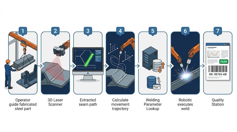
The process follows seven steps. Times are based on structural steel weldments with MIG welding.
- Part loading — the operator positions the workpiece on the positioner or fixture using an overhead crane or forklift. No programming action is required at this step. Time: 5–15 minutes depending on part weight and fixturing complexity.
- 3D scan — the laser scanner sweeps the weld joint area. Using structured light or laser triangulation, it captures a point cloud of the joint geometry at 0.2–0.5 mm resolution. Time: 45–90 seconds per metre of weld joint.
- Seam extraction — the software processes the point cloud and identifies the joint centreline, gap width, joint angle, and throat geometry. This step is fully automated. Time: 10–30 seconds per joint.
- Path generation — the system converts the extracted seam data into a complete robot trajectory, including approach path, weld pass, and retract motion. The generated path accounts for the actual joint position — not the nominal fixture position. Time: 15–45 seconds total.
- Parameter lookup — the cell matches the identified joint geometry (type, throat, material thickness) to the weld schedule library and selects the appropriate voltage, wire feed speed, travel speed, and shielding gas parameters. Time: under 5 seconds, automatic.
- Weld execution — the robot follows the generated path. A closed-loop power source monitors arc characteristics and makes micro-adjustments in real time. The positioner rotates the part to maintain optimal welding position throughout. Time: part-dependent.
- Quality logging — the controller records arc voltage, current, travel speed, and any deviation alerts for every joint, stored against the part serial number. Time: automatic, no operator input.
| Net time comparison — new part number: Traditional robotic cell:2–8 hours teach pendant programming + weld cycle Vision-guided no-programming cell:< 5 minutes scan + path generation + weld cycleFor a job shop introducing 3 new part numbers per week, this is the difference between6–24 hours of non-productive programming time and 15 minutes of scan time. |
Intelligent Welding System: This Technology in Practice
The seven-step workflow above describes the general architecture. The intelligent welding system implements it with capabilities mapped onto the structural steel challenges in this article.
- Point cloud reconstruction — weld without a CAD model. A BCW181P 3D laser profiler (1140 fps, 2600 mm field of view) converts a physical part into a 3D model within seconds, directly addressing the no-CAD scenario that offline programming cannot handle.
- Large-format line-scan camera for initial positioning. The system scans the work cell globally to locate the part first, then refines with detailed scanning — a coarse-to-fine strategy that delivers consistent positioning every cycle.
- Extended working range. Supports 7/8/9-axis gantry or cantilever configurations with working distances of 700–1700 mm — covering everything from small brackets to large girders and beams on a single platform.
- Upgraded processing power. A 12th-generation Intel Core i7 processor, 16 GB RAM, and 512 GB SSD handle dense point-cloud data in real time, with no lag or wait between scan and weld.
- Backward compatible. The system runs on a unified software platform, protecting operator training investment while the hardware scales to larger and more complex work.
| Technical note: The scanner resolution figures cited in the FAQ above (0.2–0.5 mm point-cloud resolution) reflect the specification of the 3D laser profiler used in the intelligent welding system. This is consistent with the accuracy requirements for MIG fillet welds on structural steel joints meeting AWS D1.1 throat size minimums. |
Why This Matters Specifically for Structural Steel
Structural steel is where vision-guided path generation is most valuable, due to a combination of characteristics that make it uniquely difficult for traditional programmed cells.
| Structural steel characteristic | Why vision guidance is the solution |
| Fit-up gap variation: ±1–4 mm | Path generated from actual joint geometry each cycle — not an ideal model |
| Part-to-part dimensional tolerance | Scanner captures real part position; fixture precision requirements are lower |
| High part mix: 30–80 active part numbers | No teach program library to maintain — system re-scans each part fresh |
| Heavy parts: 50–5,000 kg | Higher positioning inaccuracy with crane loading — vision compensates cycle-to-cycle |
| Mill scale and primer surface finish | Scanner reads geometry, not surface colour — unaffected by surface condition |
| AWS D1.1 / EN 1090 traceability | Joint geometry and weld parameters logged automatically per joint per part |
The fit-up gap issue in plain language
Structural steel is cut to tolerances of ±1–3 mm. When two pieces are fitted and tacked, the actual gap can vary from 1 mm on one end to 3 mm on the other. A pre-programmed path assumes a constant, drawing-dimension gap. It is not.
A vision-guided cell scans the actual gap before every weld. If the gap is wider at one end, the path adjusts travel speed and wire feed accordingly. If the joint has shifted laterally, the path shifts with it — the weld follows the real joint, as required under AWS D1.1 fillet weld size requirements.
What the technology does not solve — stated honestly
No-programming cells handle standard structural joints: fillet, butt, T-joints, lap joints. Highly complex 3D intersections — such as acute-angle tube-to-plate below 30° — may need manual path adjustment before the first production weld.
Weld schedule development for a new material grade still requires a welding engineer. The system selects from a validated library — it does not generate parameters from first principles. Budget two to four weeks for library development at commissioning.
No-Programming vs Offline Programming vs Teach Pendant: A Direct Comparison
Offline programming is often presented as the modern alternative to teach pendant work. It is worth being precise about where OLP sits relative to a true no-programming cell.
| Capability | Teach pendant | Offline programming (OLP) | Vision-guided no-programming |
| Path generation | Manual — programmer at robot | Manual — programmer at PC | Automatic — from 3D scan |
| Time per new part | 2–8 hrs | 45 min – 3 hrs | < 5 min |
| Programmer required? | Yes — robot-certified | Yes — OLP software trained | No — operator runs cell |
| Handles real part variation? | No — fixed path | No — model-based, not real-part | Yes — scans actual part each cycle |
| Part mix flexibility | Poor | Moderate | High |
| Best fit | High-volume, low-mix | Medium-mix, stable geometry | High-mix, variable geometry |
The architectural difference: offline programming removes the programmer from the robot floor, but a programmer is still writing paths. A vision-guided cell removes the programmer from the process entirely — the path does not exist until the part is scanned.
What Changes on Your Shop Floor
What does operating one of these cells actually look like, and what does it require of your team?
| Old model — traditional cell | New model — no-programming cell |
| Robot programmer: 1 FTE, $60K–$120K salary | Cell operator: redeployed from welder or machine operator, 2-week training |
| New part launch: 3–5 days (program, test, approve) | New part launch: 2–4 hours (scan, first-article weld, approve) |
| Welding engineer + programmer collaborate on each launch | Welding engineer sets weld schedule library; operator selects from menu |
| Program library: hundreds of files, version-controlled | No program library — path generated fresh from each scan |
| Quality record: manual batch inspection log | Quality log: automatic parameter record per joint, per part, in real time |

Operator skill requirements
The cell operator role in a no-programming cell is genuinely different from robot programming. The skills required are:
- Basic crane or forklift licence for part loading
- Ability to read a weld drawing and identify joint types
- Familiarity with the cell’s touchscreen HMI — scan initiation, path confirmation, alarm response
- Judgement to flag unusual scan results for engineer review — for example, a tack weld obscuring the seam, or a gap significantly outside specification
What is not required: robot programming skills, CAD knowledge, or welding certification. A production worker with no prior automation experience can be trained in two weeks.
| Workforce note: The cell operator role is typically filled by an existing welder who isredeployed from manual welding. The transition is straightforward — welders alreadyunderstand joint types, quality requirements, and weld sequence logic. They need onlylearn the cell’s scanning and confirmation workflow, not robot programming. |
Frequently Asked Questions
Does ‘no-programming’ mean the cell runs completely on its own?
No. The operator loads the part, initiates the scan, confirms the path on the touchscreen, and unloads the weldment. ‘No-programming’ means no manual path teaching — the cognitive burden of programming is eliminated, but the operator’s physical role in part handling and quality confirmation remains.
How accurate is the vision-guided path for structural steel joints?
Modern scanners achieve 0.2–0.5 mm point-cloud resolution, sufficient for MIG fillet welds with throat sizes of 4 mm and above. Path accuracy is typically ±0.3–0.5 mm on the seam centreline. A first-article verification weld is recommended before releasing any new joint type to production.
Can one cell handle both repetitive production and one-off structural work?
Yes — this is the primary use case. A single cell can weld identical parts in the morning and a one-off custom frame in the afternoon with no programming change between them. The scan-and-generate cycle takes the same time regardless of whether the part has been seen before.
What happens when the scanner cannot read the joint clearly?
The system flags the result and holds for operator confirmation. Common causes include excessive tack height obscuring the seam, heavy oxidation, or joint angle at the edge of the scanner’s field of view. The cell does not weld from an uncertain scan result — operator or engineer confirmation is required to proceed.
How long does implementation take from order to production?
Typical timeline is 8–16 weeks: four to six weeks for manufacture and factory acceptance, two to three weeks for installation and commissioning, one to two weeks for training and first-article approval. Budget two to four weeks for weld schedule library development with your welding engineer.
About the Author
Experience & Credentials
Robotic welding system integration specialist with 12+ years of direct project experience focused on Robot Positioner selection and integration. Has provided consulting to 300+ factories across North America, Europe, and Asia.
Company background: 26+ years of welding automation engineering, 40+ active patents, 1,500+ completed projects globally, approximately 70% involving Robot Positioner integration.
Certifications
- ISO 9001: 2015 (GB/T 19001-2016) — Quality Management System
- GJB 9001C-2017 — Military/Weapon Equipment Quality Management System
- EU CE — Machinery Directive 2006/42/EC (Cert. No. M.2026.206.C134866)
- High-Tech Enterprise — Cert. No. GR202341000595 (Issued Nov. 2023)
Last updated: Jun 2026
RELATED POSTS
Welding Positioner Buying Checklist: 6 Inputs for an Accurate RFQ

Robotic Laser Welding: Principles, Advantages, and Applications (2026 Complete Guide)

How Robotic Laser Welding Enables Automotive Lightweighting: From High-Strength Steel to Aluminum Bodies
Robot Positioner Payload Calculation and Safe Selection: The Complete Engineering Guide
How to Choose the Right Robotic Welding Cell for Your Shop? Single-Station vs. Two-Station (2026 Complete Guide)