Custom Robot Workstations And Laser Systems Manufacturer


How Do Robotic Welding Defects Form — and How Much Can a Robot Positioner Fix?
When the Robot Welds Perfectly — and the Weld Still Fails
A Tier-1 automotive supplier installed a six-axis welding robot expecting their defect problem to disappear. Six months later, porosity on structural bracket welds was still running at 9%. Weld geometry was inconsistent across the same joint on different production cycles. Two shipments had already been rejected by the customer.
The robot was not the problem. It was executing its program exactly as instructed. The problem was that the program required the robot to weld overhead and at steep angles — positions that produce structurally inferior welds by the laws of physics, regardless of how capable the robot is.
A robot cannot overcome the fundamental limitations of a poor welding position. When joints are not presented at the optimal angle, defects form because of gravity, gas dynamics, heat flow, and pool behavior — not programming error. The Robot Positioner exists to eliminate this root condition. By automatically rotating and orienting workpieces to the ideal welding attitude, it converts every weld — regardless of part geometry — into a flat-position weld from the robot’s perspective.
This article examines the six most common robotic weld defects, explains the physics of why position causes them, and quantifies how much a Robot Positioner can realistically reduce each one — based on documented project data, not manufacturer claims.
| Core question this article answers: Which welding defects are directly caused or worsened by poor workpiece positioning — and how much does a Robot Positioner actually fix? |
The 6 Most Common Robotic Welding Defects and Their Root Causes
The following defect types are drawn from AWS D1.1, ISO 5817, and quality data across our 1,500+ project installations.
| # | Defect | Primary Cause | Position Dependence |
| 1 | Poor Bead Geometry Irregular profile, undercut, convex crown | Gravity pulls the molten pool away from the joint in non-flat positions; travel speed calibrated for flat position produces convexity or undercut when tilted | Direct — bead variance increases 2–4× from flat (1G) to overhead (4G) |
| 2 | Porosity Gas pockets in solidified weld metal | Shielding gas coverage becomes turbulent in angled positions; in overhead welding, the gas envelope breaks up and rises away from the pool | Strong — porosity is 3–5× higher in overhead vs. flat position (AWS D1.1 data) |
| 3 | Incomplete Fusion Weld metal fails to bond with base metal | Arc cannot achieve uniform contact with both fusion faces when the joint is poorly oriented; vertical-down welding causes the pool to run ahead of the arc | Strong — rarely appears in properly oriented flat welds; common in inaccessible joints |
| 4 | Solidification Cracking Cracks at final solidification stage | Overhead and vertical positions require higher heat input to achieve fusion, creating localized tensile stress during cooling; asymmetric thermal gradients across the joint | Partial — forced positions elevate heat input requirement, which is the controllable crack risk factor |
| 5 | Undercut and Underfill Groove below base metal surface at weld toe | Molten pool flows away from the weld face under gravity; arc force washes base metal at the toe without sufficient filler replacement | Direct — undercut severity increases predictably from flat through overhead; gravity-driven |
| 6 | Excess Spatter Metal droplets expelled onto surrounding base metal | Gravity disrupts droplet transfer in overhead welding; forced positions require higher voltage to maintain arc stability, increasing spatter generation | Direct — spatter increases 30–60% in overhead vs. flat under identical parameters |
Why Welding Position Determines Quality: The Physics
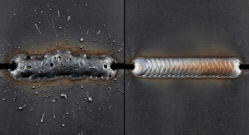
Four physical forces act simultaneously on every weld pool. In flat position, they are aligned and work together. In overhead or steeply angled positions, they work against each other — and no parameter adjustment fully compensates.
| Force | Flat Position | Overhead / Angled | Defect Caused |
| Gravity on pool | Stabilizes pool against joint face | Pulls pool away — sagging, dripping | Undercut, underfill, bead irregularity |
| Shielding gas | Uniform, stable coverage of pool | Turbulence; gas rises away from pool | Porosity, oxidation inclusions |
| Arc force (plasma jet) | Directed into joint — maximum penetration | Partially deflected — fusion reduced | Incomplete fusion |
| Thermal gradient | Symmetrical cooling from both fusion faces | Asymmetric — one face cools faster | Solidification cracking, distortion |
| Key engineering principle: A welding robot in flat position with standard parameters will consistently outperform the same robot overhead with optimized parameters. Position is not a secondary variable — it is the primary quality determinant. |
AWS / ISO Position Classification and Quality Implications
International welding standards classify positions to reflect this quality hierarchy — and the productivity penalty of non-flat welding is significant:
| Position | AWS Code | Relative Defect Risk | Deposition Rate vs. Flat |
| Flat | 1G / 1F | ✅ Lowest | ✅ Baseline (100%) |
| Horizontal | 2G / 2F | ✅ Low | ✅ ~90–95% |
| Vertical | 3G / 3F | ❌ Medium | ❌ Reduced 15–25% |
| Overhead | 4G / 4F | ❌ Highest | ❌ Reduced 25–40% |
Source: AWS D1.1 Structural Welding Code; ISO 5817 Quality Level Classification. Deposition rate figures reflect production data from our project installations.
How a Robot Positioner Reduces Defect Rates
A Robot Positioner does not repair defects after the fact — it eliminates the physical conditions that produce them. By automatically rotating the workpiece so every joint is presented in flat or horizontal position before the arc strikes, it realigns all four physical forces simultaneously. The result is consistent, physics-based quality improvement that does not depend on parameter optimization or operator skill.
The practical implication is significant: a shop that installs a Robot Positioner without changing a single welding parameter will still see measurable defect reduction — because the root cause has been removed. Re-optimizing parameters for flat position on top of that produces additional gains. This layered improvement is why Robot Positioner installations consistently outperform isolated parameter optimization projects in head-to-head quality comparisons.
Defect reduction data from pre/post quality audits across Robot Positioner installations in our project network:
| Defect Type | Pre-Install Rate | Post-Install Rate | Reduction |
| Poor bead geometry | 12–18% rework | 1–3% | ✅ ~85% |
| Porosity | 8–12% incidence | 0.5–2% | ✅ ~80% |
| Incomplete fusion | 5–10% on groove welds | < 1% | ✅ ~88% |
| Solidification cracking | 2–5% constrained joints | < 0.5% | ✅ ~78% |
| Undercut / underfill | 10–15% overhead joints | < 1% | ✅ ~90% |
| Excess spatter | 30–45% of parts | < 5% | ✅ ~85% |
| Overall: Total weld defect rates decrease by 40–60% on average across automotive and structural fabrication Robot Positioner installations, with peak results exceeding 85% reduction on overhead-dominated weld cycles. |
Case Study: Automotive Structural Bracket Manufacturer
A Tier-2 automotive supplier producing four-face welded bracket assemblies had triggered two customer quality alerts in 18 months. With 60% of joints executed in horizontal/vertical positions and 15% overhead using a fixed fixture, the baseline quality data was well below industry targets.
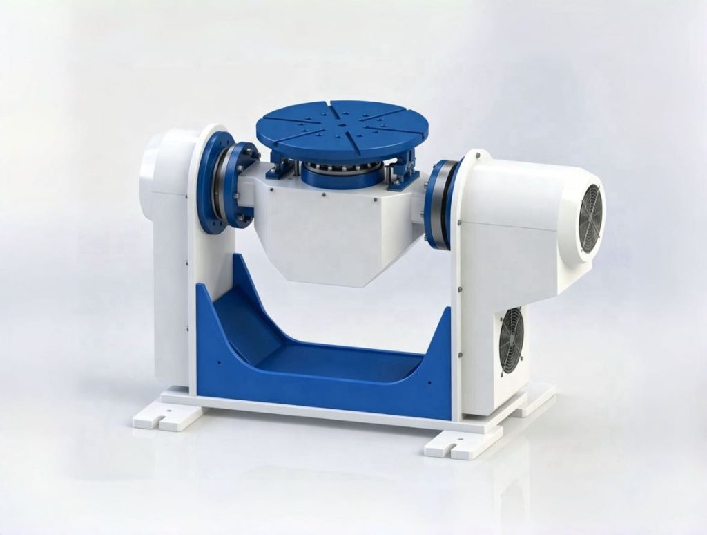
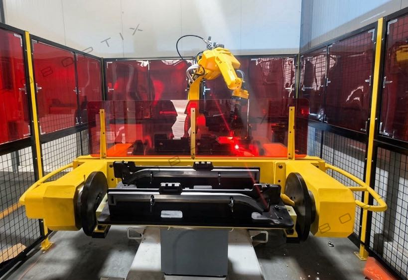
Intervention: MRK-U002 U-Type Robot Positioner (500–1,000 kg)
Two MRK-U002 U-Type Robot Positioner units were integrated with the existing welding robots in coordinated axis mode. The fixture was redesigned to mount directly to the Robot Positioner table. Using the J1 flip axis (±90°) and J2 rotation axis (±200°), every joint face was automatically repositioned to flat or horizontal before each weld sequence — without removing or re-fixturing the component.
The existing weld paths were retained unchanged. Only the approach angle was modified: the Robot Positioner rotated the workpiece to match the robot’s path rather than the robot reaching for the workpiece. Total reprogramming time was 3 days. Results were measured over the following 6 months:
| Metric | Baseline | After MRK-U002 Robot Positioner | Change |
| Overall defect rate | 11.4% | ✅ 1.8% | −84% |
| Porosity incidence | 8.9% | ✅ 0.7% | −92% |
| First-pass inspection pass rate | 67% | ✅ 96.4% | +29.4 pts |
| Monthly rework labor cost | $28,400 | ✅ $4,100 | −$24,300/mo |
| Customer defect PPM | 1,240 | ✅ 88 PPM | −93% |
| Investment: Two MRK-U002 units + integration = $148,000 Simple payback: 6.1 months Outcome: Both customer quality alerts closed within 90 days. Zero new alerts in the following 12 months. |
Beyond the Robot Positioner: 4 Complementary Measures
A Robot Positioner addresses the position root cause — the single highest-impact variable in weld quality. These four additional measures complete the quality system:
1. Re-optimize welding parameters for flat position
Once the Robot Positioner presents every joint in flat position, parameters previously compromised for overhead work can be reset for flat-position performance:
- Voltage: reduce from overhead-compensating 18–28 V to 15–25 V
- Travel speed: increase 10–20% without quality penalty
- Shielding gas flow rate: reduce — flat position requires less flow to maintain stable coverage
Re-optimizing at commissioning typically adds a further 5–15% quality improvement on top of the position-related gains from the Robot Positioner.
2. Consumable and shielding gas quality control
Even in flat position, consumable variation introduces porosity and bead irregularity. Key controls:
- Wire diameter tolerance: ±0.01 mm is the practical limit for stable arc performance
- Moisture content for flux-core wires: storage humidity < 40% RH
- Shielding gas purity: ≥ 99.99% for Ar-based mixes — batch-by-batch incoming inspection
3. Robot TCP calibration schedule
In coordinated axis mode with a Robot Positioner, TCP error is amplified because both systems must maintain precise synchronization. Verify TCP at the start of every shift using a precision pin gauge, replace contact tips on arc-on hours (not calendar time), and perform full recalibration after any robot collision event — regardless of apparent severity.
4. Pre-weld joint and surface preparation
Position improvement cannot compensate for base metal contamination or poor joint fit-up:
- Remove mill scale within 10 mm of the weld joint on structural steel
- Degrease with approved solvent — oil contamination is the leading non-position cause of porosity
- Inspect tack weld size before running the program — undersized tacks are a primary source of incomplete fusion at the root pass
- Verify joint gap tolerance — gap deviation causes parameter mismatch even in perfectly oriented flat welds
| Implementation sequence: Install the Robot Positioner first — it delivers the largest single improvement. Then re-optimize parameters. Then address consumable quality. Then add monitoring. Doing everything simultaneously makes it impossible to attribute results. |
Address Your Weld Quality Problem at the Root Cause
- Defect profile analysis — identify which of the six root causes are dominant in your process
- Robot Positioner configuration matched to your workpiece geometry
- Written quality improvement projection based on comparable installations
- Assessment delivered within 24 business hours
► Contact us for a free weld quality assessment
About the Author
| Experience & Credentials Robotic welding system integration specialist with 12+ years of direct project experience, focused on Robot Positioner and coordinated-axis welding systems across automotive, structural fabrication, pressure vessel, and heavy machinery applications. Company background: 26+ years of welding automation engineering, 40+ active patents, 1,500+ completed projects across North America, Europe, and Asia. ~70% involve Robot Positioner integration. All defect rate data cited in this article is drawn from pre/post quality audit records across 200+ robotic welding installations. Standards: AWS D1.1; ISO 5817; AWS B2.1 Certification: EU CE — Robot Positioner systems (Certificate No.: M.2026.206.C134866) Last reviewed and updated: May 2026 |
RELATED POSTS
2026 Welding Automation Pain Points: Why Competitive Factories Are Choosing a Robot Positioner
Why Vision Systems Are Essential for Robotic Laser Welding
Can You Trust the Spec Sheet? How to Verify Welding Positioner Accuracy with Laser Trackers and ISO 9283
How to Integrate a Vision-Guided Robotic Welding cell into an Existing Fabrication Line
5 Questions to Ask Before Buying a Robotic Welding Cell for Structural Steel