Custom Robot Workstations And Laser Systems Manufacturer


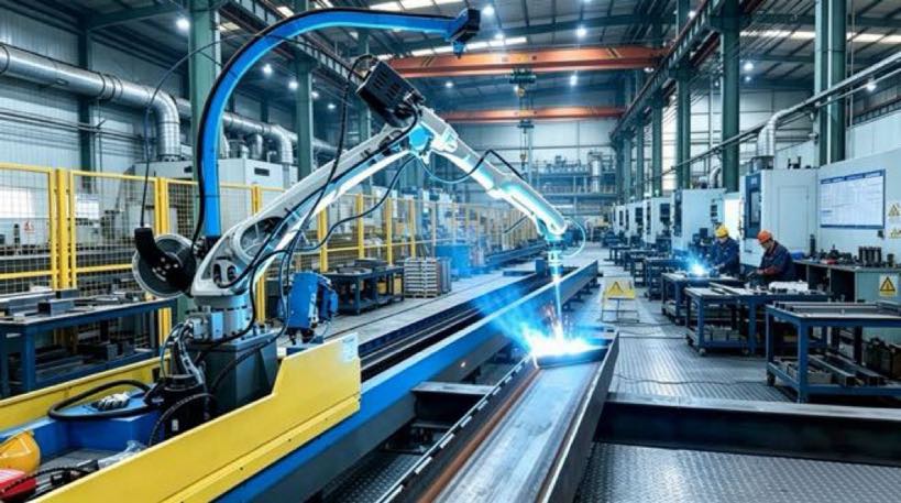
How to Integrate a Vision-Guided Robotic Welding cell into an Existing Fabrication Line
Buying a robotic welding cell is a capital decision. Integrating it into a live fabrication line without stopping production is an operational one. Most shops can justify the purchase on paper — the ROI is clear, the technology is proven, the vendor has demonstrated the cycle time. Then the cell arrives, and the real question surfaces: how do you install, commission, and ramp up a new welding workstation alongside your existing manual production without losing two weeks of output paying for the cell in the first place?
This article is for production managers and shop foremen who have approved the purchase of a vision-guided robotic welding workstation and now own the integration. It covers the practical sequence: site preparation, installation, commissioning, operator training, and production ramp-up. The focus is on no-programming robotic welding cell systems specifically — because their integration timeline is fundamentally shorter than a traditional programmed cell, and the steps differ in ways that matter.
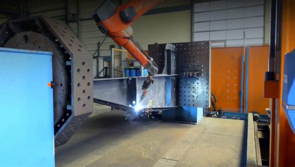
Phase 1: Site Preparation (Weeks 1–4, Overlaps with Manufacturing)
What needs to happen before the cell arrives
Site preparation is the phase most shops underestimate, because it involves trades outside welding: electrical, mechanical, and facilities. The cell cannot be commissioned until the site is ready, and site delays extend the timeline more than any other factor. Four workstreams run in parallel during the 6–10 weeks while the equipment is being manufactured:
• Electrical: Three-phase power to the cell controller (typically 380–480V, 32–63A depending on robot payload), 230V single-phase for the scanner and PLC, and a dedicated circuit for the wire feeder. Run conduit before the cell arrives — retrofitting electrical after installation adds 3–5 days.
• Compressed air: 6–8 bar clean, dry air for torch cleaning, clamping, and positioner brakes. Size the compressor for continuous duty, not intermittent. Undersized air causes intermittent clamp release and positioner drift — both produce defective welds.
• Fume extraction: Capture-at-source extraction rated for the cell’s maximum deposition rate. Structural steel welding generates 0.5–1.2 kg of fume per hour at full deposition. Recirculating filters work for mild steel; local exhaust ventilation is required for galvanised or coated material.
• Foundation: A level concrete pad rated for the combined weight of robot, positioner, and maximum weldment. For a cell with a 2,000 kg positioner and 1,500 kg part capacity, specify a 200–300 mm reinforced slab. Vibration isolation pads are recommended if the cell sits within 10 metres of precision machining equipment.
The floor layout decision
Before pouring concrete or running conduit, decide where the cell sits relative to your material flow. The most common integration mistake is placing the cell where it fits physically but not operationally — blocking crane access, creating a bottleneck between cutting and finishing, or forcing operators to walk 30 metres between stations. The cell should sit on the natural path from part preparation to post-weld processing. Material should flow in one direction; backtracking kills throughput.
| Layout factor | What to check | Common mistake |
| Crane coverage | Cell envelope must be within hook travel of your existing overhead crane | Cell placed outside crane range; manual loading triples cycle time |
| Material flow | Part enters from cutting/tacking side, exits toward inspection/finishing | Cell placed at dead-end; parts backtrack through the shop |
| Operator access | Minimum 1.5 m clearance on three sides for loading, maintenance, egress | Cell pushed against wall; maintenance requires disassembly |
| Safety zone | Light curtains or physical barriers extend 2–3 m beyond cell footprint | Insufficient safety zone; forklift traffic enters cell envelope |
Phase 2: Installation and Commissioning (Weeks 10–13)
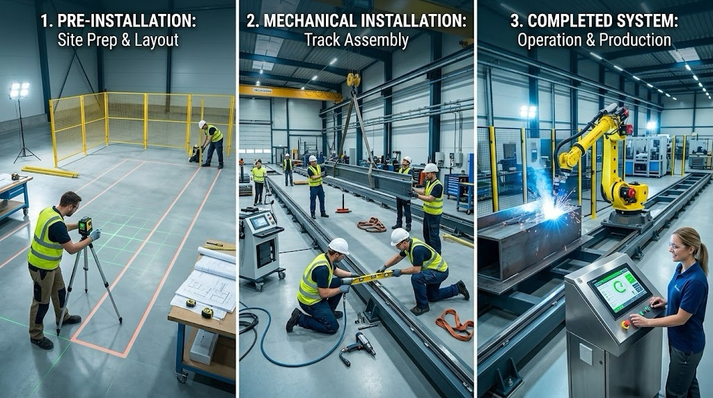
Physical installation — days 1–3
The cell arrives on a flatbed, typically in 2–4 major subassemblies: robot on base, positioner, safety enclosure, and control cabinet. Installation is mechanical: anchor the base, align the positioner to the robot’s working envelope, connect electrical and air, and mount the safety enclosure. For a no-programming robotic welding cell, the scanner and laser are pre-mounted and pre-calibrated at the factory — field calibration is limited to a reference target check, not a full recalibration. This is a 2–3 day process for a single-station cell, 4–5 days for a dual-station configuration.
Commissioning — days 4–10
Commissioning is where the cell is made production-ready on your parts. This is the phase that differs most between a traditional cell and a no-programming robotic welding cell:
| Commissioning task | Traditional cell | No-programming cell |
| Robot programming | 2–8 hrs per part. Vendor programmer on-site for 5–10 days. | Not required. Scan-and-plan generates paths autonomously. |
| First-part qualification | Program debugged on trial part; 3–5 iterations typical. | First part welded directly from scan. 1–2 parameter adjustments. |
| Weld schedule validation | Per-joint-type parameters set manually by welder. | Validated library auto-selects parameters. Operator confirms joint type. |
| Acceptance test | Programmed parts meet spec after debug cycle. | Scan-welded parts meet spec on first or second attempt. |
| Typical duration | 7–14 days | 3–6 days |
The acceptance test is the contractual milestone: the cell welds your representative part to your quality standard, and you sign off. For a no-programming cell, this test is also the strongest validation of the technology — if the cell can weld your most complex part on the first day from a cold scan, it will handle your production mix.
Phase 3: Operator Training and Production Ramp-Up (Weeks 13–16)
Who to train and how long it takes
Operator training for a no-programming robotic welding cell is shorter than most shops expect. The cell does not require programming skills; it requires loading, monitoring, and basic troubleshooting. A welder with manual experience can be trained to independent operation in 3–5 days. A non-welder (fitter, machine operator) takes 5–7 days. The difference is weld parameter awareness — a welder recognises a bad weld when they see it; a non-welder needs to learn what to look for.
Training covers four competencies:
• Part loading and clamping: Positioning the weldment in the fixture, engaging clamps, confirming the part is seated. This is the most hands-on skill and the one that most affects cycle time.
• Scan confirmation: Reviewing the 3D scan preview on the HMI, confirming the system has identified all weld joints correctly, and approving the generated path. For a no-programming robotic welding cell, this replaces the programming step entirely.
• In-process monitoring: Watching the weld in real time, recognising common issues (wire feed stutter, gas flow deviation, torch collision), and knowing when to pause vs. when to let the system self-correct.
• Daily maintenance: Torch cleaning, nozzle inspection, wire spool replacement, wire feeder clearing, and filter check. These are 15–20 minutes per shift and are the single biggest determinant of cell uptime.
The ramp-up curve
A new robotic welding cell does not reach full productivity on day one. The operator is learning, the weld schedules are being validated on production parts, and the material flow is being debugged. A typical ramp-up curve:
| Period | Productivity | What is happening |
| Week 1 | 50–65% | Operator learning load/scan/unload sequence. Cycle times longer than quoted. |
| Week 2 | 70–80% | Operator confident with standard parts. Complex parts still slow. |
| Week 3 | 85–95% | Full productivity on standard mix. Occasional slow-down on new parts. |
| Week 4+ | 95–100% | Full productivity. Operator handles new parts independently. |
| Full productivity | 100% | A no-programming cell reaches this faster — no programming bottleneck for new parts. |
Ramp-up speed depends more on the operator than the technology. A motivated operator involved in commissioning from day one reaches full productivity in 2–3 weeks. An operator assigned on the day the cell goes live takes 4–6 weeks. Involve your operator early.
Phase 4: Running Alongside Manual Production
The transition strategy that works
Few shops switch off manual welding the day the cell starts. The transition is gradual — and it should be. The cell takes on the highest-volume, most repeatable parts first, while manual welders handle complex, low-volume, or oversized work. This is the correct division of labour: the cell does repeatable, high-deposition welding at consistent quality; the manual welder handles complex positioning, one-off fabrications, and rework.
The most effective transition sequence:
• Weeks 1–2: Run the cell on your top 3 part numbers by volume. Manual welders continue all other work. Compare cell output quality and cycle time against manual baseline.
• Weeks 3–4: Expand to top 8–10 part numbers. Redeploy one manual welder to cell operator. Remaining welders focus on complex and oversized parts.
• Weeks 5–8: Cell handles full standard production mix. Manual welders handle custom, oversized, and rework only. The cell produces 60–80% of total shop welding output by volume.
What not to do
Do not attempt to run every part through the cell in the first week. The operator is still building confidence, the material flow is not yet smooth, and forcing complex parts through a new cell produces defects that erode operator trust. Trust takes weeks to build and one bad day to destroy. Start simple, prove the technology, then expand.
| The integration is not complete when the cell is installed. It is complete when your operator trusts the system enough to load a part they have never seen before, press start, and walk away to prepare the next one. That trust is earned through 3–4 weeks of successful production, not through a commissioning demo. |
Frequently Asked Questions
How long does it take to integrate a robotic welding cell into an existing line?
From order to full productivity: 14–18 weeks for a no-programming robotic welding cell, 18–24 weeks for a traditional programmed cell. The difference is commissioning and ramp-up: a no-programming cell eliminates per-part programming, cutting 5–10 days from commissioning and 1–2 weeks from ramp-up. Site preparation (4 weeks) and equipment manufacturing (6–10 weeks) are the same for both types.
Do I need to stop production during installation?
No. Installation and commissioning happen in a designated area that does not interfere with existing manual welding stations. The cell runs independently during commissioning. The only disruption is during physical placement (1–2 days of crane and forklift activity) and electrical tie-in (half day of power isolation).
What happens if the cell breaks down in production?
The parts the cell was welding go back to manual welding — this is why a gradual transition is important. Your manual welders are still on staff during the first 2–3 months. For breakdowns, the vendor should provide remote diagnostics within 4–8 hours and on-site service within 24–72 hours. Specify response time in your purchase agreement.
Can I move the cell to a different location later?
Yes, but plan for 3–5 days of disassembly, transport, reinstallation, and recalibration. The scanner and robot maintain calibration through transport if moved as a subassembly; full disassembly requires a factory recalibration visit.
How do I justify the integration cost to my team?
Frame it as risk reduction. The cell reduces dependency on hard-to-hire welders, eliminates rework on repeatable parts, and increases capacity without adding headcount. Run the ROI model from Blog 08 with your actual numbers — the payback period for a vision-guided robotic welding workstation typically falls within 5–10 months for shops with 80+ parts per month and loaded welder rates above $50/hour.
Next Steps
If you are planning a robotic welding cell integration, here is what to do:
• Walk your shop floor with a tape measure and identify the installation location before ordering. Crane coverage, material flow, and floor load capacity are your three constraints.
• Involve your facility manager and electrician in the site preparation plan from week one. Electrical and air requirements are in the vendor’s site prep guide — request it before purchase.
• Select your cell operator now — not when the cell arrives. The operator should participate in commissioning and acceptance testing. This is the single biggest factor in ramp-up speed.
• Plan a gradual transition: cell on top 3 parts first, manual welders on everything else. Do not attempt full production on day one.
| Related reading in this series: Blog 03 — No-Programming Robotic Welding Cell: How Vision-Guided Systems Eliminate Teach Pendants Blog 08 — ROI of a No-Programming Robotic Welding Cell: A Practical Guide Blog 09 — 5 Questions to Ask Before Buying a Robotic Welding Cell for Structural Steel |
Talk to Our Welding Automation Engineers
Tell us your part mix, joint types, and monthly volume. We will run a cycle time study on your representative part and return a detailed estimate. No commitment required.
Contact Us Now
→ Talk to an Engineer First
✓ No commitment required ✓ Response within 24 hours ✓ Free cycle time estimate
About the Author
Experience & Credentials
Robotic welding system integration specialist with 12+ years of direct project experience focused on Robot Positioner selection and integration. Has provided consulting to 300+ factories across North America, Europe, and Asia. All specification data in this article is drawn from actual H / B / L / U series product datasheets.
Company background: 26+ years of welding automation engineering, 40+ active patents, 1,500+ completed projects globally, approximately 70% involving Robot Positioner integration.
Certifications
- ISO 9001: 2015 (GB/T 19001-2016) — Quality Management System
- GJB 9001C-2017 — Military/Weapon Equipment Quality Management System
- EU CE — Machinery Directive 2006/42/EC (Cert. No. M.2026.206.C134866)
- High-Tech Enterprise — Cert. No. GR202341000595 (Issued Nov. 2023)
Last updated: Jun 2026
RELATED POSTS
5 Reasons Large Workpiece Welding Is Inefficient — and How a Robot Positioner Solves Each One
Can You Trust the Spec Sheet? How to Verify Welding Positioner Accuracy with Laser Trackers and ISO 9283

A Comprehensive Comparison of Robotic Laser Welding vs. MIG and TIG Welding: Which One Is Right for You?
No-Programming Robotic Welding Cell:How Vision-Guided Systems Eliminate Teach Pendants
Robot Positioner ROI: How Much Is Manual Welding Actually Costing You?