Custom Robot Workstations And Laser Systems Manufacturer



Why a 2-Ton Positioner Can’t Always Hold a 2-Ton Part: Eccentric Loading, Overturning Moment, and Inertia
A positioner rated for 2,000 kg looks, on paper, like it should hold any 2,000 kg part. In the field, it frequently cannot — and the failure is not a defect, it is a misunderstanding of what the rating means. The 2-ton figure assumes a load centered on the rotation axis at the rated radius. Real fabrications have their center of gravity offset, accelerate and decelerate, and present moment loads the simple weight number never captured.
This article explains the three forces that quietly erode a positioner’s real capacity: eccentric loading, overturning moment, and inertia. Understanding them is the difference between spec-ing a positioner that holds your part and one that strains, sags, or fails to hold it accurately.
Note: Capacity methodology below reflects ROBOPTIX positioner engineering practice and is cross-referenced with peer-reviewed research on positioning accuracy under load (Park et al., 2019, Applied Sciences; Liu et al., 2023, Materials).
1. The 2-Ton Fallacy
The payload rating on a positioner is measured under specified, idealized conditions: a load of stated mass, centered on the rotation axis (or at a defined radius for tilt axes), at a defined speed, at ambient temperature. Change any of those and the effective capacity changes with it. The rating is a point on a curve, not the whole curve.
1.1 What “2,000 kg” Really Means
- Centered: Mass is balanced about the rotation axis, so no overturning moment is generated.
- At rated radius: For tilt axes, the load sits at the radius the rating was derived for — not cantilevered far out.
- Steady speed: No aggressive acceleration or emergency stops that spike dynamic load.
A long beam, an off-center bracket, or a part welded while the axis indexes between passes violates all three assumptions at once. The 2-ton number becomes, at best, optimistic.
2. Eccentric Loading: When the Center of Gravity Moves
Every part has a center of gravity (CoG). When that CoG sits on the rotation axis, the load is pure weight. When it sits off-axis — as it almost always does on real weldments — the part generates a moment equal to its weight times the offset distance. The further the CoG from the axis, the larger the moment the positioner must resist.
2.1 The Moment Beats the Mass
Two parts can weigh exactly the same yet demand completely different positioner performance. A 2,000 kg cube centered on the chuck is easy. A 2,000 kg beam mounted at one end has its CoG a meter or more from the axis, creating an overturning moment the payload number never accounted for. The positioner is no longer just supporting weight — it is resisting a lever.
Rule of thumb: for a tilt or rotate axis, evaluate the overturning moment (weight × CoG offset), not the weight alone. The moment rating is the real limit.
3. Overturning Moment: The Real Limit
Overturning moment is the rotational force that tries to tip or twist the positioner axis. It is calculated as M = W × d, where W is the weight and d is the perpendicular distance from the rotation axis to the CoG. A positioner’s structural and drive limit is set by the moment it can hold, and that limit is reached long before the mass limit when loads are offset.
3.1 Worked Example
Take a 2,000 kg part with its CoG 0.8 m from the rotation axis. The overturning moment is 2,000 kg × 0.8 m = 1,600 kg·m. If the same positioner is rated for, say, 1,200 kg·m of overturning moment at speed, the part exceeds the real limit despite being under the 2,000 kg mass rating. The positioner either sags, drifts, or cannot hold the commanded angle — and the weld lands wrong.
- Cantilever penalty: Mounting a load at one end (cantilever) maximizes d and therefore M. The same mass centered between head and tail stocks minimizes it.
- Tilt-axis sensitivity: Tilt axes fight gravity directly; an off-center load on a tilt axis is the harshest case for overturning moment.
4. Inertia: The Dynamic Load You Forget
Static weight is what the part weighs at rest. Inertia is what it demands while moving. Every time the axis accelerates or decelerates, the effective load spikes above the static weight by an amount proportional to mass times acceleration. Fast indexing between weld passes can briefly multiply the demand.
4.1 Acceleration Magnifies Everything
A positioner that rotates a heavy, off-center part at high speed must both resist the overturning moment and supply the torque to accelerate the part’s rotational inertia. The dynamic torque can exceed the static moment by a wide margin during start-stop cycles — exactly the duty profile of multi-pass robotic welding, where the axis creeps, indexes, and reverses constantly. Ignoring inertia is the most common cause of a positioner that “tests fine empty but struggles under the real part.”
5. How to Calculate Real Capacity
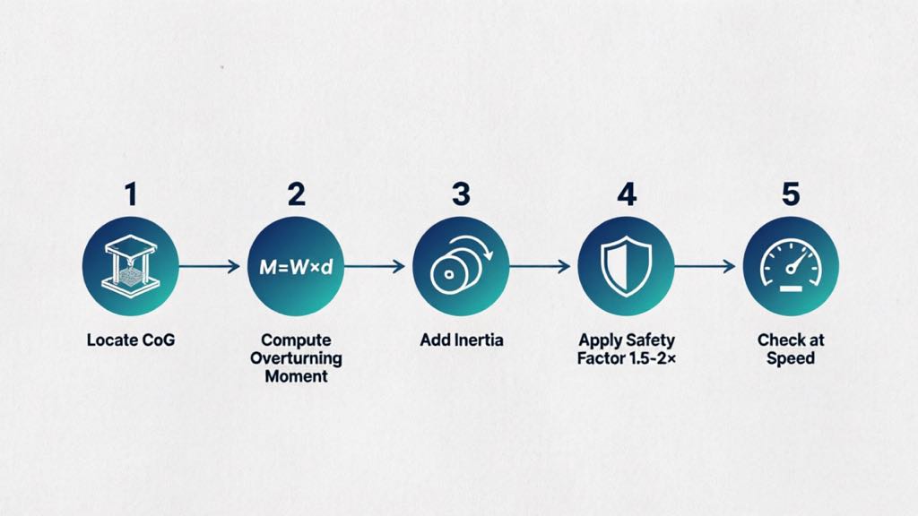
Sizing a positioner properly means computing the moment and inertia demands of your actual part, not reading the mass rating. A practical method:
- Locate the CoG: From CAD or by weighing, find the center of gravity and its offset from each rotation axis.
- Compute overturning moment: M = W × d for each axis; compare to the positioner’s moment rating, not its kg rating.
- Add inertia: Estimate peak acceleration torque from mass, radius of gyration, and max angular acceleration.
- Apply safety factor: Use 1.5–2× on moment and inertia to cover estimation error, wear, and shock loads.
- Check at speed: Confirm the limit holds at the rotation speed you will actually run, not just at crawl.
ROBOPTIX positioners are specified with both payload and overturning-moment ratings, and the application team sizes them against your part’s actual CoG and duty cycle rather than the catalog mass number. The B001–B004 head-tail series and B008–B012 multi-axis servo units publish moment limits alongside payload so the real constraint is visible before purchase.
6. Field Example: The “Within Rating” Failure
A ROBOPTIX customer selected a positioner on mass alone for a 1,800 kg frame whose CoG sat 1.1 m off the tilt axis. The mass was under the 2,000 kg rating, but the overturning moment exceeded the axis limit. Under welding, the frame sagged a few millimeters at the far end and the robot seam drifted. Re-specifying to a positioner with adequate moment capacity — at nearly the same mass rating — eliminated the sag and restored first-pass yield. The lesson: the mass rating was never the binding constraint; the moment was.
7. When the 2-Ton Fallacy Doesn’t Bite
Demands candor: for many parts, the simple mass rating is perfectly adequate. The eccentricity and inertia effects are small when:
- The part is compact with its CoG near the rotation axis
- Rotation is slow and indexing is gentle (low acceleration)
- The load is centered between head and tail stocks, not cantilevered
In those cases, a positioner sized on mass alone will perform as advertised. The fallacy only bites on the long, off-center, fast-cycling parts where moment and inertia dominate — which, not coincidentally, are the parts positioners are most often bought to handle.
Frequently Asked Questions
Q: Why can’t a 2-ton positioner hold a 2-ton part?
A: Because the 2-ton rating assumes a centered load at the rated radius and steady speed. A real part with an off-center center of gravity generates an overturning moment and, under acceleration, inertia — both of which the mass rating ignores. The binding limit becomes moment, not mass.
Q: What is overturning moment in simple terms?
A: It is the rotational force a load exerts because its weight is offset from the rotation axis: moment = weight × distance from axis to center of gravity. A cantilevered part creates a large moment even at modest weight.
Q: How much safety factor should I use?
A: Apply 1.5–2× on both overturning moment and inertia to cover estimation error, component wear, and shock loads from abrupt stops. Size to the factored demand, not the raw number.
Q: Does a centered part avoid these problems?
A: Largely yes. With the center of gravity on the rotation axis and gentle motion, eccentric moment and dynamic inertia stay small, and the mass rating becomes a reliable guide. The issues grow with offset, speed, and cantilever mounting.
A 2-ton positioner holding a 2-ton part is the exception, not the rule, because the rating describes an idealized centered, steady load. Eccentric loading shifts the center of gravity off-axis and creates an overturning moment; inertia adds a dynamic spike during every acceleration and stop. Together they can cut real usable capacity well below the nameplate mass — sometimes dramatically, as the cantilever penalty shows.
The fix is to size on moment and inertia, not mass. Locate the center of gravity, compute the overturning moment for each axis, add the dynamic inertia demand, and apply a safety factor before comparing to the positioner’s published limits. ROBOPTIX specifies positioners with explicit moment ratings and validates them against your part’s actual geometry and duty cycle, so the number you buy on is the number you weld with. For long, off-center, or fast-cycling weldments — the parts positioners exist to handle — that discipline is the difference between a cell that holds and a cell that sags.
Sizing on moment, not mass? Contact ROBOPTIX with your part’s weight, center of gravity, and duty cycle for a load-and-moment validated positioner recommendation.
About the Author
Experience & Credentials
Robotic welding system integration specialist with 12+ years of direct project experience focused on Robot Positioner selection and integration. Has provided consulting to 300+ factories across North America, Europe, and Asia. All specification data in this article is drawn from actual H / B / L / U series product datasheets.
Company background: 26+ years of welding automation engineering, 40+ active patents, 1,500+ completed projects globally, approximately 70% involving Robot Positioner integration.
Certifications
- ISO 9001: 2015 (GB/T 19001-2016) — Quality Management System
- GJB 9001C-2017 — Military/Weapon Equipment Quality Management System
- EU CE — Machinery Directive 2006/42/EC (Cert. No. M.2026.206.C134866)
- High-Tech Enterprise — Cert. No. GR202341000595 (Issued Nov. 2023)
Last updated: Jun 2026
References
[1] Park, J.-H., Kim, S.-H., Moon, H.-S., & Kim, M.-H. (2019). Influence of Gravity on Molten Pool Behavior and Analysis of Microstructure on Various Welding Positions in Pulsed Gas Metal Arc Welding. Applied Sciences, 9(21), 4626.
[2] Liu, J., Jiang, F., Chen, S., Xu, B., Zhang, G., Cheng, W., & Ma, X. (2023). Mechanisms of Gravitational Influence on Weld Pool Behavior and Weld Bead Performance in Variable Polarity Plasma Arc Welding across Different Welding Position. Materials, 16(19), 6457.
RELATED POSTS
Robot Positioner ROI: How Much Is Manual Welding Actually Costing You?
7th Axis Robot Track System Maintenance & Troubleshooting Guide
Welding Positioner Buying Checklist: 6 Inputs for an Accurate RFQ
2026 7th Axis Robot Selection Guide: Payload, Stroke, Repeatability & Brand Compatibility
Robot Positioner Payload Calculation and Safe Selection: The Complete Engineering Guide