Custom Robot Workstations And Laser Systems Manufacturer


Transformer Tank Welding Automation:Solving the Challenge of Large, Non-Repetitive Parts
Transformer tank welding sits at the intersection of everything that makes welding automation difficult. The tanks are large — often 2 to 6 metres in their longest dimension. Each one is effectively unique, with panel layouts, corrugation patterns, and connection port positions that vary by transformer rating and customer specification. The joints are numerous: a single medium-power transformer tank may have 40 to 80 individual weld joints, many of them in confined locations between cooling fins, reinforcing ribs, and lifting lugs.
Conventional robotic welding cells were not designed for this. They were designed for repetitive parts with stable geometry — automotive brackets, pipe fittings, standardised structural sections. A traditional robot cell in a transformer tank environment spends more time being reprogrammed than welding, because every tank variant is, from the robot’s perspective, a new part.
This article explains why transformer tank welding has historically resisted automation, what specific technical capabilities are required to automate it successfully, and how zero-programming, vision-guided welding systems address each challenge that conventional cells cannot.
This article is part of the Structural Steel Welding Automation series. If you are new to vision-guided robotic welding cells, Blog 03: No-Programming Robotic Welding Cell provides the foundational context before reading this vertical application article.
Why Transformer Tank Welding Has Resisted Automation
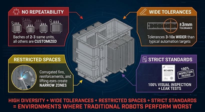
To understand the solution, it helps to be precise about the problem. Transformer tanks fail the basic assumptions of conventional robotic welding on four counts simultaneously.
1. No two tanks are identical
Power transformers are engineered-to-order products. Tank dimensions, wall thickness, panel count, corrugation depth, bushing positions, and lifting attachment locations all vary by electrical specification. A fabricator producing 15 to 30 transformer tanks per month may have only two or three units of the same configuration in any given production batch. The remainder are one-offs or low-volume variants.
A conventional robotic cell requires a separate teach program for each configuration. At three to eight hours per program, a 25-variant monthly batch requires 75 to 200 hours of programmer time — before a single arc opens. For most transformer tank fabricators, this calculation ends the automation conversation.
2. Dimensional tolerances are wider than typical automation targets
Transformer tank panels are fabricated from heavy plate — typically 4 to 16 mm wall thickness — using flame cutting, plasma cutting, and press forming. The resulting dimensional tolerances are ±1 to 3 mm on panel dimensions, ±2 to 4 mm on corrugation pitch, and ±1 to 3 mm on fit-up gap at weld joints. These are standard tolerances for this fabrication method; they are also three to ten times wider than the tolerances conventional robotic welding paths assume.
3. Joint access geometry is constrained and variable
Transformer tanks are assembled structures with internal baffles, external cooling fins, valve connections, and reinforcing channels that create restricted access zones. The robot torch must navigate between these features to reach the weld joint — and the exact configuration of obstructions varies from unit to unit based on the transformer rating and customer specification.
4. Weld quality standards are stringent
Transformer tanks operate under continuous oil pressure in service. IEC 60076 and customer factory specifications typically require 100% visual inspection and leak testing, with many customers specifying additional non-destructive testing on primary seams. The quality gap between what a fixed programmed cell produces and what the specification requires is the core obstacle.
| The transformer tank automation paradox: High part variety + wide dimensional tolerances + constrained access + stringent quality standards= exactly the conditions where conventional robotic cells perform worst. And exactly the conditions where manual welding creates the most bottleneck. |
What Makes Transformer Tank Welding Automatable in 2026
Three technology developments, arriving in combination, have changed the feasibility calculation for transformer tank welding automation.
Development 1: Zero-programming path generation from 3D scan
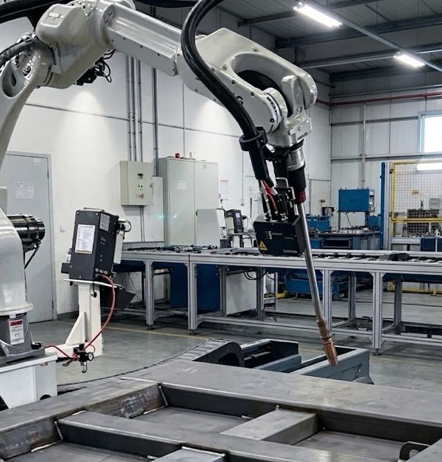
Vision-guided welding systems equipped with 3D laser scanners can capture the actual geometry of each transformer tank panel assembly before welding begins. The scan detects the real joint positions — not the nominal positions from a drawing — and generates the robot weld path from what it actually finds. Because the path is generated fresh from each scan, part-to-part dimensional variation is irrelevant.
Development 2: Gap-adaptive weld parameter control
A 3D scan does not just locate the seam — it measures the gap width along the entire joint length. This data drives gap-adaptive parameter control: the welding system adjusts wire feed speed, travel speed, and torch oscillation continuously along the joint to maintain consistent weld throat and leg size despite varying gap width. For transformer tank seams where the fit-up gap varies from 0.5 mm to 3 mm along a single panel joint, gap-adaptive control is the difference between a weld that passes leak testing and one that requires rework.
Development 3: Digital twin collision verification
A full-size virtual simulation of the workcell — the digital twin — runs the complete weld sequence before the first arc opens on any new tank configuration. The simulation checks every robot position for collision with the tank structure, the fixture, and the positioner. This eliminates the primary risk of automated welding on a new part configuration: the first-article crash.
The Automated Transformer Tank Welding Process — Step by Step
The workflow below describes how a vision-guided, zero-programming welding system handles a transformer tank body from panel assembly to completed weld.
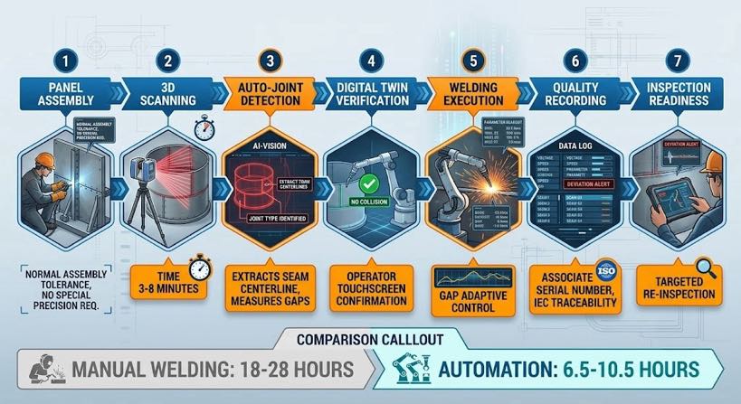
- Panel assembly and tack welding — panels assembled in the fixture and tack welded at intervals. Dimensional accuracy at this stage is to normal fabrication tolerance (±1–3 mm). No special precision required.
- 3D scan of assembled structure — the laser scanner sweeps the assembled tank, capturing geometry of all accessible weld joints: base-to-wall seams, wall-to-wall corner seams, corrugation root welds, reinforcing rib attachment welds, and lifting lug pad welds. Scan time: 3 to 8 minutes depending on tank size and joint count.
- Automatic joint detection and seam extraction — the vision system identifies each joint type from the scan geometry, extracts the seam centreline, measures the actual gap profile along each joint, and flags joints outside programmable tolerances for operator review.
- Digital twin verification — the generated weld sequence runs in full-size virtual simulation. Collision detection checks every approach, weld, and retract motion against the actual tank geometry from the scan. The operator reviews the simulation on the touchscreen and confirms before proceeding.
- Weld execution — the robot executes the verified sequence. Gap-adaptive parameter control adjusts wire feed and travel speed continuously along each joint. The positioner rotates the tank between joint groups to maintain flat or horizontal welding position throughout.
- In-process quality logging — arc parameters, travel speed, and deviation alerts logged per joint throughout the weld sequence, against the tank serial number, for IEC 60076 traceability.
- Post-weld inspection prep — the completed tank is presented for visual inspection. The weld log directs inspector attention to joints where deviation alerts occurred during welding.
| Cycle time comparison — medium transformer tank (approx. 2.5 m × 1.5 m × 1.5 m, 60 joints): Manual welding: 18–28 hours (2–3 shift-days) Traditional robotic cell: Not viable — reprogramming time exceeds weld time Vision-guided automated system: Scan + verify: 15–25 min | Weld cycle: 6–10 hours Total: 6.5–10.5 hours (1–1.5 shift-days) Throughput gain: approximately 2–3× on weld cycle time, plus elimination of programming overhead. |
Transformer Tank Joint Types and Their Automation Challenges
| Joint type | Location | Automation challenge | Vision-guided solution |
| Flat panel butt weld | Base plate seams | Gap variation from plasma cut edges; panel bow | 3D scan measures actual gap profile; gap-adaptive parameters maintain throat size throughout |
| Wall-to-base fillet weld | Perimeter seam at tank bottom | Long continuous seam; thermal distortion accumulates | In-weld arc tracking corrects torch position; positioner presents joint in flat-down position |
| Corrugation root weld | Corrugated side panel to flat frame | Tight access between corrugations; pitch variation ±2–4 mm | Scan detects actual corrugation pitch; path generated to match real spacing, not nominal drawing |
| Corner weld (wall-to-wall) | Vertical seams at tank corners | Variable gap; full-penetration required on pressure-retaining seams | Gap measurement at scan; multi-pass path planned based on actual gap — 1 to 3 passes |
| Reinforcing rib fillet | External stiffening ribs on tank wall | Variable standoff from wall curvature; rib positioning tolerance ±3 mm | Vision locates actual rib position; fillet path generated from real rib-to-wall intersection |
| Lifting lug pad weld | External pads at lift points | High-constraint weld — full fusion required | Digital twin verifies torch access; gap-adaptive control ensures full fusion at pad perimeter |
| Bushing seating weld | Tank lid — bushing flange to lid plate | Circular seam on lid; angular approach required | Circular weld path generated from scan of actual bushing flange position |
The Physical Cell Configuration for Transformer Tank Welding
Robot and reach
A standard 6-axis industrial robot with a 1,400 to 2,800 mm reach handles most medium transformer tank configurations. For large power transformer tanks — 4 to 6 metres in length — a 7th-axis linear track extends the robot’s operating range along the tank length without requiring the part to be repositioned. The 7th-axis track is coordinated with the robot controller so linear motion is synchronised with the weld path.
Positioner
A headstock/tailstock positioner — typically 2,000 to 10,000 kg payload rating for distribution and power transformer tanks — rotates the tank to present each joint group in the optimal welding position. The positioner is coordinated with the robot controller and the scan system: the scan captures joint positions relative to the positioner zero point, and the weld sequence plans positioner rotations between joint groups automatically.
Safety and fume management
Transformer tank welding involves high deposition rates on heavy plate — fume generation is significant. The cell enclosure includes high-volume extraction at the source plus area extraction for the full enclosure. Arc flash protection meets IEC 60079 and local safety codes. The cell is interlocked to prevent robot motion when access doors are open.
Weld Quality and Traceability for IEC 60076 and Customer Specifications
| Quality requirement | Manual welding approach | Automated cell approach |
| 100% visual inspection | Inspector examines all joints post-weld; no process record | Weld log provides actual arc parameters per joint; inspector reviews log alongside visual check |
| Pressure/leak testing | Pass/fail — no process linkage if test fails | Weld log identifies joints with deviation alerts; targeted re-inspection if test fails |
| Weld procedure qualification (WPS/PQR) | Welder qualifies per AWS D1.1 or EN 15614 | Cell welds to validated weld schedule library — parameters traceable to qualification test records |
| Dimensional verification | Manual gauge measurement — sample basis | Gap measurement from pre-weld scan provides predicted weld size; arc log confirms execution |
| Material traceability | Manual records linking plate heat numbers to joints | Weld log linked to part serial number; plate heat number entry at job setup |
Frequently Asked Questions
Can automated welding handle corrugated panel seams?
Yes — corrugated panel welding is one of the specific applications where vision-guided automation outperforms both manual welding and conventional robotic cells. The 3D scan detects actual corrugation pitch and geometry, which varies from the nominal drawing dimension due to press forming tolerances. The weld path is generated to match the real corrugation spacing, producing significantly more consistent weld size than manual welding over a long corrugation run.
What is the minimum and maximum tank size the system can handle?
The practical size range is approximately 0.8 metres to 6 metres in the longest dimension, with part weights from 200 kg to 15,000 kg depending on positioner rating. Smaller tanks — distribution transformers below 100 kVA — can be welded on a standard dual-station cell without a 7th-axis track. Larger power transformer tanks — 6 metres and above — require a gantry-mounted robot or multi-robot system. The most common production range for automation implementation is 400 kVA to 10 MVA distribution and medium power transformer tanks.
How does the system handle tanks where the customer specification changes between orders?
Because the weld path is generated from each tank’s actual scan rather than a stored program, specification changes between orders require no programming update. The operator loads the tank, initiates the scan, and the system generates a new path appropriate to the geometry it finds. Weld schedule library updates — if the specification change involves a different joint class or material thickness — require welding engineer input, but this is a one-time update per new joint configuration, not a per-order programming task.
What operator skills are required to run the cell on transformer tank production?
The cell operator requires: crane or forklift licence for tank loading; ability to read a weld drawing and identify joint sequences; familiarity with the cell’s touchscreen HMI; and basic understanding of what constitutes an unacceptable scan result. Robot programming skills, CAD knowledge, and welding certification are not required. A technician with general fabrication shop experience can be trained in two to three weeks.
Next Steps
- To understand the 3D scanning and seam tracking technology that makes this possible, read Blog 04: 3D Vision Laser Seam Tracking Explained.
- To understand how scan data is converted into a weld program through reverse modeling , read Blog 05: Scan-to-Weld Technology.
- To evaluate the ROI case for your transformer tank production volume and current labour cost, read Blog 08: ROI of a No-Programming Robotic Welding Cell.
- To understand how to integrate an automated welding cell into an existing fabrication line, read Blog 10: How to Integrate a Vision-Guided Robotic Welding Workstation.
| See How Vision-Guided Welding Works on Your Actual Parts Send us a tank drawing, a Tekla model, or just a photo of the joint. We’ll run a scan-to-weld path demonstration and return a cycle time estimate, path preview, and weld cross-section — no commitment required. ✉ Contact Us Now → Calculate My ROI ✓ No commitment required ✓ Response within 24 hours ✓ Free cycle time estimate |
About the Author
Experience & Credentials
Robotic welding system integration specialist with 12+ years of direct project experience focused on Robot Positioner selection and integration. Has provided consulting to 300+ factories across North America, Europe, and Asia.
Company background: 26+ years of welding automation engineering, 40+ active patents, 1,500+ completed projects globally, approximately 70% involving Robot Positioner integration.
Certifications
- ISO 9001: 2015 (GB/T 19001-2016) — Quality Management System
- GJB 9001C-2017 — Military/Weapon Equipment Quality Management System
- EU CE — Machinery Directive 2006/42/EC (Cert. No. M.2026.206.C134866)
- High-Tech Enterprise — Cert. No. GR202341000595 (Issued Nov. 2023)
Last updated: Jun 2026
RELATED POSTS
Future Trends of Robot 7th Axis Robot in Smart Factories & Cobot Integration (2026-2030)
Real-World Robotic Welding Cell Applications in General Industry: Case Studies 2026
No-Programming Robotic Welding Cell: Vision-Guided, No Teach Pendant

A Comprehensive Comparison of Robotic Laser Welding vs. MIG and TIG Welding: Which One Is Right for You?
Manual vs Robotic Welding for Structural Steel:When Does Automation Pay Off?