Custom Robot Workstations And Laser Systems Manufacturer


How to Install and Integrate a 7th Axis Robot: Step-by-Step Guide & Best Practices
“A 7th axis robot arrived last week. The manual has 200 pages. Where do we start?”
This is the most common question I hear. Based on 200+ field installations, this guide walks you through every step from floor preparation to first production run.
Part 1: Pre-Installation Preparation & Safety
Complete these 5 critical steps before unboxing:
1. Floor inspection— Measure flatness across full track length. Requirement:±1mm per 3 meters. Use self-leveling compound if needed.
2. Anchor planning— Mark bolt hole locations per layout drawing. Drill 100-150mm deep. Use chemical anchors.
3. Layout verification— Place track sections in position. Verify robot reaches all stations. Check cable drag chain clearance.
4. Safety zone planning— A 7th axis robot creates a larger hazard zone. Install safety fencing at least 500mm beyond max reach.
5. Tool preparation— Precision level, laser alignment tool, torque wrench, lifting equipment.
Safety First:Lock out/tag out all power sources before mechanical installation.
Part 2: Mechanical Installation — Step by Step
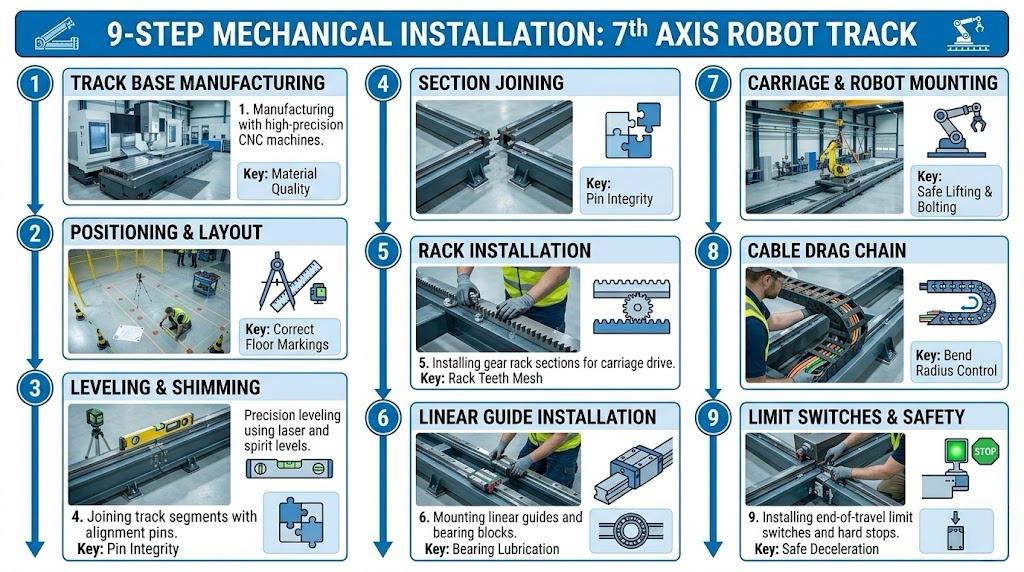
Step 1: Track base manufacturing (pre-installation)
High-quality 7th axis robot starts with proper manufacturing: high-strength steel/cast iron → stress relief → CNC machining → straightness within 0.1mm per meter.
Step 2: Track positioning— Place first section at home position. Align with layout marks.Do not bolt yet.
Step 3: Leveling (most critical step)— Place precision level on rail surface. Adjust leveling bolts. Target:±0.5mm over full length. Use laser for long tracks.
Step 4: Section joining— Butt sections with alignment pins. Rail joint step under 0.1mm. Torque bolts (200-300 Nm). Install splice plates.
Step 5: Rack installation— Clean surface. Install from home position. Maintain joint gap 0.5-1.0mm. Use alignment fixture.
Step 6: Linear guide installation— Clean surface. Install reference rail first. Align second rail parallel. Pre-load bearing blocks.
Step 7: Carriage and mounting plate— Place carriage on guides. Install mounting plate. Verify level. Mount robot. Torque to spec.
Step 8: Cable drag chain— Lay along track. Ensure minimum bend radius. Leave 10-15% cable slack.
Step 9: Limit switches and home sensor— Install hard limits at both ends. Install home sensor. Test before powering.
Part 3: Electrical Integration, Servo Tuning & Programming
Step 10: Electrical connection— Connect servo drive to power. Connect feedback cables. Connect drive to robot controller (EtherCAT/Profinet/DeviceNet). Ground properly.
Step 11: Robot controller configuration
- Fanuc:Configure external axis. Set axis parameters. Assign I/O. Test jog.
- ABB:Add external axis in RobotStudio. Configure drive parameters. Calibrate.
- KUKA:Configure external axis in WorkVisual. Set kinematic model. Master axis.
Step 12: Servo tuning— Start with auto-tuning. Adjust gain/integral/derivative values. Test step response. Target:no visible vibration, minimal following error.
Step 13: Coordinate calibration— Define coordinate system. Teach home position. Verify positive direction. Test multiple positions.
Step 14: Safety integration— Connect STO to safety relay. Test e-stop. Verify light curtains. Document all tests.
Step 15: First motion test— Clear area. Jog at 10% speed. Listen for unusual noises. Verify limit switches. Increase speed gradually to 100%.
Part 4: Common Problems and Solutions
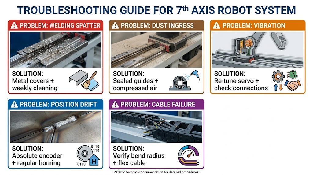
| Problem | Root Cause | Solution |
| Welding spatter damage | Spatter on rails and rack | Install metal covers/bellows; use IP67 motors; clean weekly |
| Dust ingress | Dust enters linear guides | Use sealed guides; positive pressure; daily compressed air |
| Vibration | Poor servo tuning or loose connections | Re-tune servo; check connections; reduce acceleration |
| Position drift | Thermal expansion or encoder drift | Home regularly; use absolute encoders; allow warm-up |
| Cable chain failure | Exceeded bend radius or wrong cable | Verify bend radius; use continuous flex cable; inspect monthly |
Part 5: Protection System Design
Why protection is critical:A 7th axis robot in welding/grinding environments faces constant spatter and dust. Without protection, components fail within months.
Metal covers (recommended for welding):Galvanized or stainless steel. Telescoping design. Extremely durable. Disadvantages: heavier.
Bellows (recommended for dust):Neoprene-coated fabric. Accordion-style. Lightweight, fully sealed, lower cost. Disadvantages: can be burned by spatter.
Protection selection guide:
| Environment | Recommended Protection | Additional Measures |
| Heavy welding (carbon steel) | Metal covers | IP67 motors, weekly cleaning |
| Light welding | Metal or bellows | Anti-spatter spray |
| Grinding/casting | Metal + sealed guides | Positive pressure |
| Clean room | Bellows | Low-particle materials |
Part 6: Our Integration Service Experience
With 1,500+ global projects and 200+ field installations, our process:
- Pre-installation survey (1 day)— Measure floor, verify anchors, identify obstacles
- On-site installation (2-5 days)— Mechanical install, laser leveling, electrical integration, servo tuning
- Programming & testing (1-2 days)— Configure external axis, develop test programs, verify cycle time
- Training (1 day)— Daily operation, maintenance checklist, troubleshooting, safety
- Documentation— As-built drawings, maintenance schedule, spare parts list, commissioning report
Customer feedback:
“Your technician arrived Monday. By Thursday afternoon, our 7th axis robot was welding. The training was thorough — our maintenance team now handles everything.” — Automotive Tier 1 supplier
“We tried installing another supplier’s 7th axis robot ourselves. After three weeks, we hired your team. You had it running in 4 days.” — Heavy equipment manufacturer
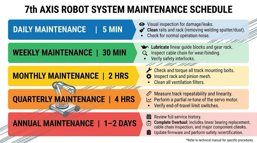
Part 7: Maintenance Schedule
| Frequency | Tasks |
| Daily (5 min) | Visual inspection, clean rails, listen for noise, verify home |
| Weekly (30 min) | Lubricate rails and rack, inspect drag chain, check limit switches, wipe covers |
| Monthly (2 hrs) | Full mechanical inspection, check rack wear, inspect bearing blocks, test e-stop |
| Quarterly (4 hrs) | Measure repeatability, re-tune servo if needed, replace worn wipers, re-torque anchors |
| Annual (1-2 days) | Complete system inspection, replace damaged covers, consider recalibration |
Coming Next in Part 5
Title:7th Axis Robot for Welding Applications: Real-World Case Studies & ROI Analysis
Covers:Three welding case studies, before/after productivity comparisons, actual ROI calculations, lessons from 50+ installations
Take Action Now
You have learned the complete 7th axis robot installation process. Now apply this knowledge to your project.
We provide complete 7th axis robot integration services:Pre-installation survey, mechanical installation, electrical integration, servo tuning, training, documentation.
Author Identification
I am a robotic welding system integration expert with 12+ years of industry experience specializing in 7th axis robot installation and integration. My company has 26+ years of expertise, holds 40+ patents, and has completed 1,500+ global projects. I have personally supervised over 200 field installationsofrobotic 7th axis systems.
Updated: May 2026
References & Engineering Compliance Standards
- Civil & Foundation Tolerances:
- ACI 117-10:American Concrete Institute specification for heavy industrial flooring, establishing the global benchmark for the ±1mm leveling criteria required by high-speed linear tracks.
- ISO 230-1:2012:Test code for geometric and kinematic straightness measurement of multi-section linear beds using laser interferometry.
- Mechanical Metrology & Gearing Standards:
- AGMA 2015-1-A01:International standard for establishing structural backlash, pitch alignment, and joint gap parame ters ($0.5mm∼1.0mm$) inindu strisl rack-and-pinion drive units.
- VDI 2861:Association of German Engineers guide for precision handling and kinematic splicing of linear guide rails under dynamic structural loads.
- Manufacturer OEM Integration Protocols:
- FANUC B-83284EN Manual:Core engineering reference for setting up independent/synchronized external axes on R-30iB controllers, including real-time servo tuning and gain mitigation.
- ABB 3HAC050941-001 Manual:Technical database for loading external track profiles within RobotStudio and synchronizing MultiMove cross-talk via Profinet/EtherCAT.
- KUKA WorkVisual KSS 8.6:Software configuration manual for integrating non-KUKA external linear motors into the robot’s native kinematic transformation matrix.
- Functional Safety & Risk Assessment:
- EN ISO 10218-1:2011 / ANSI/RIA R15.06-2014:Industrial Robots and Robot Systems Safety Requirements. This framework governs the 500mm absolute hazard clearance calculations and dual-channel STO (Safe Torque Off) wiring protocols utilized across our 1,500+ global deployments as of May 2026.
RELATED POSTS
How to Integrate a Vision-Guided Robotic Welding cell into an Existing Fabrication Line
How a Welding Positioner Controls Gravity: The Physics of Puddle Stability and Weld Quality
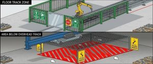
Floor Track vs Overhead 7th Axis Robot: Installation, Safety & Selection Guide
Welding Positioner for Sale: How to Choose the Right Type for Your Part (Headstock Tailstock, L-Type, U-Type, Horizontal 3-Axis, Single Axis Rotary, Vertical Tilting)

A Comprehensive Comparison of Robotic Laser Welding vs. MIG and TIG Welding: Which One Is Right for You?