


Custom Robot Workstations And Laser Systems Manufacturer


Coordinated Motion Programming: Making Your Robot and Positioner Move as One Kinematic Chain
Most factories buy a robot and a positioner as two machines. They wire them together, run the robot program, and trigger the positioner with a digital output between passes. The result “works”—until you look at the weld. The torch stops at every index, the arc restarts cold, the seam shows a ripple at each joint, and first-pass yield never reaches what the brochure promised. The problem is not the equipment. It is that the two machines were never programmed as one.
This article explains coordinated motion programming: the practice of treating the positioner as an integral axis of the robot controller so both move from a single trajectory. We cover external-axis interpolation, EtherCAT synchronization, path smoothing, and the weld-quality payoff of keeping the tool center point (TCP) at constant speed. The goal is a cell where the robot and positioner are not two devices that cooperate—they are one kinematic chain.
Note: Coordination methodology reflects ROBOPTIX positioner integration practice across servo-driven cells, cross-referenced with peer-reviewed research on position-dependent weld-pool behavior (Park et al., 2019, Applied Sciences; Liu et al., 2023, Materials) and ISO 9283 robot performance test methods.
1. “Integration” Is the Wrong Goal
Integration implies two independent systems connected at the edges. Trigger-based control—robot welds a pass, sends a signal, positioner rotates, robot resumes—is integration. It is also why so many cells underperform. Every time the positioner moves, the robot is parked; every time the robot moves, the positioner is parked. The weld is built in discrete, stop-start chunks, and the defects accumulate at every boundary between them.
The better goal is coordination: one controller plans one trajectory that includes both the robot’s six axes and the positioner’s rotation axes. The positioner becomes part of the robot’s own kinematic model. When that happens, the arc never stops because the positioner never has to wait its turn.
2. One Kinematic Chain: The Positioner as an Extension of the Robot
Kinematically, a welding cell is a tree of links. The robot base is the root, the robot axes are branches, the torch is the end effector, and the workpiece is held by the positioner. In coordinated motion, the positioner axes are added to the same kinematic chain the robot controller solves, so moving the positioner is mathematically the same operation as moving a robot joint. The controller no longer sees “robot + positioner”; it sees one longer arm reaching through the part.
2.1 Axis 7, 8, and 9 in the Controller
Most industrial controllers let you declare external axes—commonly the positioner’s rotate and tilt axes—and assign them to the same motion group as the robot. Once declared, the positioner is axis 7, 8, or 9 in the controller’s internal coordinate solution. A single move instruction can now command the robot and the positioner simultaneously, and the controller computes the combined inverse kinematics so the torch follows the intended path on the part. The external axis is not a peripheral; it is a joint the planner optimizes alongside the robot’s own.
2.2 One Trajectory, Not Two Programs
With the positioner externalized, you no longer maintain a robot program and a separate positioner program. You maintain one trajectory. The path is defined in the workpiece (or a user) frame, and the controller distributes the required motion between robot and positioner automatically. If the part needs to stay flat while the seam travels, the controller tilts the positioner and moves the robot together to keep the weld in the 1G/2G band—exactly the position control P02 described, now executed continuously rather than in discrete steps. One program means one source of truth for where the weld should be.
3. External-Axis Interpolation
Interpolation is how the controller fills the space between two taught points with smooth motion. In standalone mode, the robot interpolates its own six axes. In coordinated mode, the controller interpolates the robot axes and the external positioner axes together, solving for a synchronized path where the share of motion between them is decided frame by frame to keep the TCP on the weld. This is the heart of coordination: not two interpolators running in parallel, but one interpolator that owns all the axes.
3.1 Calibrating the Positioner Frame to the Robot Base
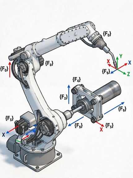
Coordinated motion is only as accurate as the frame relationship between robot and positioner. Before the first coordinated move, the positioner’s zero must be calibrated to the robot base frame—typically by jogging the robot TCP to known datums on the positioner chuck or faceplate, or by a laser or ballbar calibration. Get this wrong and the controller’s combined kinematics are built on a false premise: the robot will “think” the part is somewhere it is not, and the weld will be offset by a constant or rotating error. This frame calibration is the single most skipped step in field startups, and the single most common cause of “the program runs but the weld is wrong.”
4. EtherCAT Synchronization and the Sync Frame
For the robot and positioner to move as one, their drives must share a common time base. A positioner lagging the robot by even a few milliseconds produces a visible seam defect, because the two motions are no longer geometrically consistent at the instant of welding—the torch is on one point of the path while the part has drifted slightly behind. Synchronization is what keeps them locked.
4.1 Distributed Clocks and Jitter
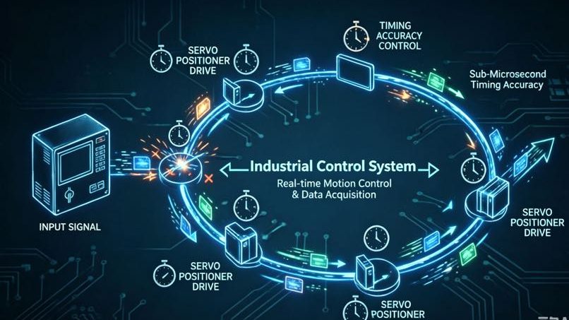
EtherCAT with distributed clocks gives every servo drive a synchronized timestamp, so the robot and positioner axes execute their commanded positions at the same control instant. The “sync frame” is the network message that locks them. Jitter—variation in that timing—is the enemy. ROBOPTIX servo positioners use EtherCAT distributed-clock synchronization so the positioner axis tracks the robot’s motion group with sub-millisecond consistency, which is what lets a continuous weld span a rotating part without a cold restart. Where older analog or pulse-train links introduced tens of milliseconds of drift, EtherCAT keeps the chain tight. The practical test is simple: command a coordinated helical move and scope the axis timing; if the positioner lags, the seam tells you before the oscilloscope does.
5. Constant TCP Speed Through the Weld
The payoff of coordination is constant tool-center-point speed. In trigger-based cells the TCP alternates between full speed and zero at every index; in coordinated cells the TCP moves through the weld at one steady rate while the positioner rotates the part beneath it. The robot tracks the path; the positioner supplies the rotation; neither stops.
5.1 Why Stops and Starts Wreck the Weld
When the arc stops and restarts, the weld pool cools and re-melts, leaving a cold lap, an unfused restart, or a visible ripple, and heat input spikes at each restart. Constant TCP speed—achieved because the positioner carries the rotation while the robot maintains the torch path—keeps heat input uniform and the bead profile consistent. This is the same physics Park and Liu document for position-dependent pool behavior: holding the weld in a consistent gravitational and positional band stabilizes the pool, and coordinated motion is what holds that band continuously instead of in stationary steps (Park et al., 2019; Liu et al., 2023).
6. Path Smoothing and Blended Motion
Even with coordination, a naive program creates corners: the trajectory passes through each taught point and decelerates to satisfy accuracy. Path smoothing—often called blending or corner rounding—lets the controller cut the corner with a defined radius, so the TCP never fully stops. The positioner and robot share the blended path, and the weld flows through what would otherwise be a hard stop. The trade-off is real: excessive smoothing sacrifices accuracy at the corner, so the radius is tuned per application—tight on precision root passes, looser on long fillets. Coordinated cells expose this as a single parameter set across robot and positioner, rather than two independent smoothing settings that fight each other and produce a seam that looks different on every pass.
7. The Gravity Constant: How Coordination Protects Weld Quality
Coordinated motion is not just smoother; it is a quality control. By continuously rotating the part to keep the weld in the flat or horizontal band, the cell holds a near-constant gravity vector at the pool—the single biggest determinant of puddle stability—instead of letting the pool swing through vertical and overhead zones as the part is repositioned in steps.
7.1 Position-Dependent Pool Behavior
Peer-reviewed work shows weld-pool behavior and bead quality vary sharply with welding position, because gravity drains and destabilizes the pool in overhead and vertical orientations (Park et al., 2019, on GMAW positions; Liu et al., 2023, on VPPA across positions). Coordinated motion turns that finding into a cell design rule: keep the pool in the flat/horizontal band by moving the part, not by stopping to reposition. The positioner does the rotating; the robot does the tracking; the controller keeps them as one. The result is the flat-position quality of P02, sustained through the entire seam rather than reset at every index. In other words, coordination is how you operationalize the gravity physics from P01 across a whole part.
8. Three Failures That Break Coordinated Programs
Coordinated motion fails in predictable ways. Knowing them shortens a startup from weeks to days, because each has a specific fix rather than a vague “the cell feels wrong.”
8.1 Frame Mismatch, Sync Drift, Positioner Singularity
- Frame mismatch: The positioner zero was never calibrated to the robot base, so the combined kinematics are offset. Fix: run the frame calibration before the first coordinated move, and re-verify it after any mechanical change to the cell.
- Sync drift: The network link allows timing jitter, so the positioner lags the robot. Fix: use a synchronized fieldbus (EtherCAT distributed clocks) and verify sync with a scoped test move rather than assuming the link is tight.
- Positioner singularity: At certain tilt angles the positioner loses mechanical authority or the controller hits a kinematic limit, forcing a stop mid-weld. Fix: plan the path to avoid the positioner’s singular orientations, or add a redundant axis so the robot can take over the motion through that zone.
9. Field Example: A 3-Axis Cell Tuned for Smooth Motion
A ROBOPTIX customer ran a 2-axis positioner beside a 6-axis robot in trigger mode: the robot welded a 300 mm pass, signaled the positioner to index 15°, repeated. First-pass yield stalled near 80% with cold-lap defects at every index, and the cell was about to be re-quoted with a faster robot. After re-configuring the positioner as external axes 7–8 in the robot controller, calibrating the positioner frame, and enabling EtherCAT sync with path blending, the cell ran the seam as one continuous trajectory at constant TCP speed. Index defects disappeared, and first-pass yield rose above 97%. The hardware did not change—the programming model did. Coordination, not more equipment, was the fix, and it cost a fraction of the proposed robot upgrade.
10. When Coordination Is Not Worth the Effort
Coordination is not free, and for some work it is overkill. If your part is welded in a single position with no rotation between passes—a short seam on a fixture that already presents it flat—trigger-based control is perfectly adequate, and the added setup of frame calibration and sync verification buys you little. Coordination pays off when the weld travels around a part that must rotate continuously, when first-pass yield is throttled by restart defects, or when you are already investing in a servo positioner whose precision the trigger model cannot use. Spend the engineering where the defect rate lives; skip it where a simple signal does the job.
Frequently Asked Questions
Q: What is the difference between integrating and coordinating a positioner?
A: Integration connects two standalone systems that take turns: the robot welds, then signals the positioner to index. Coordination treats the positioner as an external axis in the robot controller so both move from one trajectory. Coordination removes the stop-start cycle that causes cold-restart defects and uneven heat input.
Q: Do I need EtherCAT to coordinate robot and positioner motion?
A: You need a synchronized fieldbus with a common time base. EtherCAT with distributed clocks is the common choice because it keeps axis timing within sub-millisecond jitter; analog or pulse-train links typically drift enough—tens of milliseconds—to show as seam defects during a continuous weld.
Q: Why does the positioner frame calibration matter so much?
A: Coordinated motion solves combined kinematics from the robot base through the positioner to the part. If the positioner’s zero is mis-calibrated to the robot frame, every coordinated move is built on false geometry and the weld lands offset. It is the most skipped startup step and the most common cause of a program that runs but welds wrong.
Q: Can coordinated motion really improve weld quality, or just speed?
A: Both, but quality is the stronger effect. Constant TCP speed and continuous part rotation keep the pool in a stable gravitational band, eliminating cold-restart defects. Research on position-dependent pool behavior (Park, 2019; Liu, 2023) supports holding a consistent welding position for bead quality—and coordination is how you hold it through the whole seam.
Treating a positioner as a separate machine that the robot “talks to” caps your cell at stop-start quality. Coordinated motion programming removes that ceiling: declare the positioner as external axes in the robot controller, calibrate its frame to the robot base, synchronize the drives on a common time base with EtherCAT distributed clocks, and let one trajectory drive both. The weld then runs at constant TCP speed with the part continuously rotated to hold the flat/horizontal band—exactly the gravity-stable condition research ties to better pools.
ROBOPTIX servo positioners (the B008–B011、B012 multi-axis units) ship EtherCAT-ready and are configured as external axes in major robot controllers, with application support for frame calibration and sync verification. For cells where first-pass yield matters more than raw cycle time, coordination is the upgrade that pays for itself in defect reduction rather than hardware.
The next article in this series takes the accuracy question further: how to verify, with laser trackers and ISO 9283, that the coordinated cell actually holds the repeatability the spec sheet claims.
Ready to coordinate your cell?
Contact ROBOPTIX with your robot brand and part geometry for an external-axis configuration and frame-calibration plan.
About the Author
Experience & Credentials
Robotic welding system integration specialist with 12+ years of direct project experience focused on Robot Positioner selection and integration. Has provided consulting to 300+ factories across North America, Europe, and Asia. All specification data in this article is drawn from actual H / B / L / U series product datasheets.
Company background: 26+ years of welding automation engineering, 40+ active patents, 1,500+ completed projects globally, approximately 70% involving Robot Positioner integration.
Certifications
- ISO 9001: 2015 (GB/T 19001-2016) — Quality Management System
- GJB 9001C-2017 — Military/Weapon Equipment Quality Management System
- EU CE — Machinery Directive 2006/42/EC (Cert. No. M.2026.206.C134866)
- High-Tech Enterprise — Cert. No. GR202341000595 (Issued Nov. 2023)
Last updated: Jun 2026
References
[1] Park, J.-H., Kim, S.-H., Moon, H.-S., & Kim, M.-H. (2019). Influence of Gravity on Molten Pool Behavior and Analysis of Microstructure on Various Welding Positions in Pulsed Gas Metal Arc Welding. Applied Sciences, 9(21), 4626.
[2] Liu, J., Jiang, F., Chen, S., Xu, B., Zhang, G., Cheng, W., & Ma, X. (2023). Mechanisms of Gravitational Influence on Weld Pool Behavior and Weld Bead Performance in Variable Polarity Plasma Arc Welding across Different Welding Position. Materials, 16(19), 6457.
RELATED POSTS
Robotic Welding Cell vs Traditional Welding Line: What Actually Changes on Your Shop Floor
The Pre-Purchase Audit: A Factory Visit Checklist and Bench Test Protocol for Welding Positioner Buyers
What Is a Robotic Welding Cell? 2026 Beginner’s Guide | 37 Shop Data
Anatomy of a Robotic Welding Cell: Core Components & Selection Guide (2026)
Robotic Welding Cell Programming for Beginners: Step-by-Step Guide 2026
