Custom Robot Workstations And Laser Systems Manufacturer


Robot Positioner Payload Calculation and Safe Selection: The Complete Engineering Guide
The 15% That Causes 80% of Early Failures
A factory in Texas installed a Robot Positioner rated at 1,000 kg. Three months into production, the gearbox developed an audible grinding noise and the drive unit began tripping thermal overload protection twice per shift. An investigation revealed the issue immediately: the engineer had entered the workpiece net weight of 820 kg into the selection form. The fixture weighed 230 kg. The actual working load was 1,050 kg — 5% over the nominal rating — and the asymmetric center of mass added an eccentric moment the selection had not accounted for. The effective dynamic load was approximately 1,380 kg, 38% above the rated capacity.
Across our 1,500+ Robot Positioner installation records, approximately 15% of early-stage mechanical failures are directly traceable to payload calculation errors made at the selection stage. The failure modes are consistent: premature gearbox wear, bearing spalling, encoder drift from vibration, and in severe cases, structural fatigue in the drive head. All of these are preventable.
This article provides a complete, step-by-step payload calculation methodology, explains the three load types that must be considered, defines appropriate safety factors for different operating conditions, and gives model-specific specification data for safe selection across the H, B, L, and U series.
| Who this article is for: Design engineers specifying Robot Positioners, purchasing engineers verifying supplier quotations, and project managers validating integration proposals. If you are new to Robot Positioners, read the Beginner’s Guide first, then return here. |
The Three Load Types You Must Calculate
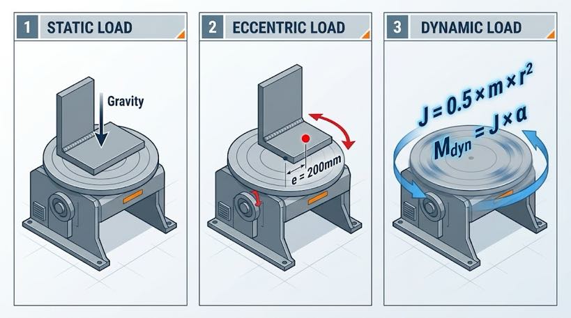
The rated payload on a Robot Positioner datasheet is not simply the maximum workpiece weight. It represents the system’s capacity to handle the combined effect of three distinct load types simultaneously:
| Load Type | Definition | Calculation Method | Commonly Overlooked Situations |
| Static Load | Gravity force of workpiece + fixture on the rotation axis at rest | Weigh or calculate from CAD: Wₜₒₜₐₗ = Wᵂᵒʳʰᵖᵉᶜᵉ + Wᶠᵊˣᵗᵘʳᵉ | Multi-part fixtures; run-on tabs, ground clamps, and measurement tooling left mounted during rotation |
| Eccentric Load | Additional bending moment when the workpiece center of mass is offset from the rotation axis centerline | Mₑᶜᶜ = Wₜₒₜₐₗ × g × eₜ (e = offset distance in meters) | L-shaped weldments; cantilevered sub-assemblies; asymmetric fixtures; post-tack distortion shifting mass |
| Dynamic Load | Inertial torque generated when the positioner accelerates or decelerates | Mₑ₁ₙ = J × α (J = rotational inertia kg·m², α = angular acceleration rad/s²) | Large-diameter workpieces (inertia scales with r²); frequent high-speed face changes; positioner mounted on a servo track |
| Key principle: A Robot Positioner’s rated payload is its capacity to handle all three load types in combination, not workpiece static weight alone. Using only net workpiece weight in your selection calculation is the single most common specification error — and the root cause of most early mechanical failures. |
4-Step Payload Calculation Method
Step 1 — Total Static Weight
Formula: Wₜₒₜₐₗ = Wᵂᵒʳʰᵖᵉᶜᵉ + Wᶠᵊˣᵗᵘʳᵉ + Wₐᵈᵈₐₜᵒʳᵊᵉˢ
- Use the heaviest workpiece variant in your production mix, not the typical or average weight
- Include all fixture elements: clamping plates, locating pins, welding ground tabs, run-on/run-off blocks
- If direct weighing is not possible, calculate from material density: steel = 7,850 kg/m³; aluminum = 2,700 kg/m³
Step 2 — Eccentric Moment
Formula: Mₑᶜᶜ = Wₜₒₜₐₗ × 9.81 × e (N·m, where e = horizontal offset of center of mass from rotation axis, in meters)
- Symmetric workpieces (circular tube, round disc): eccentric offset typically < 50 mm, usually negligible
- Asymmetric workpieces (L-brackets, cantilevered booms, multi-lug weldments): offset may reach 200–600 mm, must be calculated
- Compare calculated Mₑᶜᶜ against the model’s published allowable moment — this parameter is in the full technical datasheet, not always on the summary spec card
| Worked example: Workpiece 800 kg + fixture 150 kg + accessories 30 kg = Wₜₒₜₐₗ = 980 kg. Center of mass offset e = 200 mm. Mₑᶜᶜ = 980 × 9.81 × 0.200 = 1,923 N·m This eccentric moment must be within the target model’s allowable J1 or rotation axis moment rating. For MRK-U001: J1 allowable torque = 2,695 N·m. 1,923 N·m < 2,695 N·m — margin exists, but is only 29%. Verify against dynamic loads before confirming selection. |
Step 3 — Dynamic Load Estimate
For applications with frequent face changes or high rotation speeds, estimate rotational inertia:
Simplified inertia (solid cylinder approximation): J = 0.5 × m × r² (kg·m²)
Use maximum outer radius as r. Angular acceleration α = max speed (rad/s) ÷ acceleration time (s). Dynamic torque Mₑᵉₙ = J × α.
- Mₑᵉₙ < 30% of rated drive torque: acceleration loads are manageable; standard selection applies
- Mₑᵉₙ = 30–60% of rated drive torque: review acceleration ramp setting; avoid abrupt stops
- Mₑᵉₙ > 60% of rated drive torque: reduce maximum speed or select next-larger torque model
Step 4 — Apply Safety Factor and Confirm Selection
Selection load = Wₜₒₜₐₗ × Safety Factor
| Operating Condition | Recommended Safety Factor | Rationale |
| Symmetric workpiece, low speed (<30°/s), infrequent repositioning | 1.20–1.25 | Low eccentric and dynamic contribution; standard margin sufficient |
| Asymmetric workpiece or medium speed (30–60°/s) | 1.25–1.35 | Eccentric moment and dynamic torque are meaningful contributors |
| High eccentricity or high speed (>60°/s) or frequent repositioning | 1.35–1.50 | Dynamic loads are significant; larger margin required |
| Overweight workpieces (>2,000 kg) or safety-critical stations | 1.50 | Conservative selection; consequences of failure are severe |
| Continuing the worked example: Wₜₒₜₐₗ = 980 kg, asymmetric bracket, rotation speed 45°/s → Safety Factor = 1.35 Selection load = 980 × 1.35 = 1,323 kg Conclusion: MRK-U002 (rated 500–1,000 kg) is undersized. Next valid options: MRK-B002 (1,000–1,500 kg head-and-tailstock) if the workpiece geometry suits it, or MRK-B011 three-axis (1,000–1,500 kg) for multi-face requirements. |
Accuracy Selection: Matching Repeatability to Application
Positional repeatability (expressed in mm at a specified radius) defines how consistently the Robot Positioner returns to the same angular position across repeated cycles. This is one of the most misunderstood parameters in Robot Positioner specifications.
| Accuracy Level | Typical Models | Suitable Applications | Not Appropriate For |
| ±0.03 mm@R500 | B009, B011 | Automotive load-bearing structures, precision equipment bases, aerospace structural weldments | General structural steel (over-specified; adds cost without benefit) |
| ±0.05 mm@R350 | H series, B001/B002, U001 | Automotive components, engineering machinery precision parts, pressure vessels | Applications where weld seam offset >0.2 mm would trigger rejection |
| ±0.075 mm@R500 | B004, U002 flip axis, B010 | Heavy structural fabrication, construction machinery, mining equipment | Automotive Tier-1 supply chain (may not meet customer CPK requirements) |
Practical selection rule: the Robot Positioner’s repeatability should be no greater than one-third of the total allowed weld position tolerance in the applicable standard or customer specification. This preserves margin for robot TCP error (±0.03–0.05 mm typical) and fixture manufacturing tolerance.
Safety Requirements and Installation Checklist
Electrical grounding — the most overlooked safety item
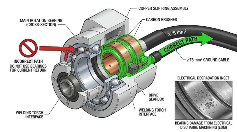
Critical rule: welding current must return through the positioner’s dedicated ground slip ring, never through the standard rotation bearings. High-frequency welding current passing through unprotected bearings causes electrical discharge machining (EDM) damage — micro-pitting of the rolling elements that typically appears within 6 to 12 weeks of operation. Symptoms: increasing noise, vibration, then catastrophic bearing seizure.
- Verify: the target model includes a dedicated welding current return path (slip ring or brush assembly)
- Verify: welding ground cable cross-section meets the model’s minimum requirement (L002: ≥75 mm²)
- Verify: ground cable connection is made before first arc, not after commissioning
Overload warning signs — what to monitor
| Symptom | Likely Cause | Action | If Ignored |
| Grinding or knocking noise during rotation | Bearing damage or gear surface pitting | Stop production; request supplier inspection | Complete bearing seizure; spindle locked |
| Drive unit trips thermal overload repeatedly | Sustained overload or cooling obstruction | Verify actual working load against rated capacity | Drive power module thermal failure |
| Repeatability fails periodic check | Gearbox backlash increase or encoder loosening | Measure backlash; contact supplier if out of spec | Weld position drift; customer rejections |
| Foundation bolts repeatedly loosen | Vibration from imbalanced load or inadequate base | Re-torque; inspect workpiece balance; reinforce base | Equipment displacement; weld seam offset |
Pre-installation checklist
| Foundation & Mechanical ☐ Concrete foundation strength ≥ C25 (25 MPa); thickness ≥ 200 mm for light models, ≥ 400 mm for B004/B008 ☐ Installation levelness ≤ 0.5 mm/m (verified with precision level) ☐ Foundation bolts torqued to specification; schedule re-torque check at 500 hours ☐ Safety barrier or light curtain installed at rotation envelope boundary (≥ 1 m clearance) Electrical & Control ☐ Welding current ground path confirmed via slip ring — NOT through bearings ☐ Ground cable cross-section verified against model specification ☐ Servo encoder cables are shielded; single-point shield grounding ☐ Emergency stop signal wired into robot controller safety circuit (synchronized stop) ☐ Coordinated axis parameters verified with robot integrator before first arc |
Need a Load Calculation Review for Your Application?
Our engineering team will perform a complete payload analysis for your specific workpiece — static load, eccentric moment, dynamic torque estimate, and safety factor recommendation — and deliver a written model recommendation within 24 business hours, at no cost.
► Submit your workpiece data for a free load calculation and selection review
About the Author
| Experience & Credentials Robotic welding system integration specialist with 12+ years of direct project experience focused on Robot Positioner selection and integration. Has provided consulting to 300+ factories across North America, Europe, and Asia. All specification data in this article is drawn from actual H / B / L / U series product datasheets. Company background: 26+ years of welding automation engineering, 40+ active patents, 1,500+ completed projects globally, approximately 70% involving Robot Positioner integration. Certifications ISO 9001: 2015 (GB/T 19001-2016) — Quality Management System GJB 9001C-2017 — Military/Weapon Equipment Quality Management System EU CE — Machinery Directive 2006/42/EC (Cert. No. M.2026.206.C134866) High-Tech Enterprise — Cert. No. GR202341000595 (Issued Nov. 2023) Last updated: May 2026 |
RELATED POSTS
Five-Year TCO of a Welding Positioner: Counting the Hidden Costs the Quote Forgot
Welding Positioner Buying Checklist: 6 Inputs for an Accurate RFQ
Robotic Welding Cell vs Manual Welding: Which Is Better for Modern Manufacturing?
How to Choose the Right Robotic Laser Welding System for Your Factory
7th Axis Robot in Welding Automation: Real Case Studies and ROI Examples