Custom Robot Workstations And Laser Systems Manufacturer


5 Reasons Large Workpiece Welding Is Inefficient — and How a Robot Positioner Solves Each One
The Hidden Productivity Crisis in Large Workpiece Welding
A pressure vessel fabricator in Texas ran two shifts per day, six days a week. On paper, the operation looked productive. In practice, a time-motion study revealed that welders spent fewer than 30% of their working hours actually welding. The rest — repositioning, waiting for cranes, adjusting fixtures, reworking awkward passes — was invisible waste embedded so deeply into daily operations that the team had stopped seeing it.
This is the defining challenge of large workpiece welding: the bigger and heavier the part, the more time production loses to everything except welding.
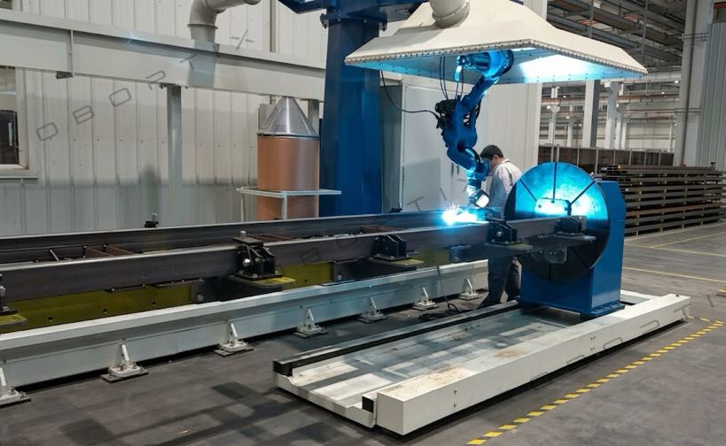
Engineering machinery booms, pressure vessels, wind turbine towers, heavy vehicle chassis, ship structural sections — these are not components you can flip by hand, reposition with a jig, or weld from a single fixed station. Large workpiece welding requires overhead cranes, multi-person coordination, extended setup time, and constant positional compromise. And every one of those requirements costs time, money, and weld quality. This is precisely where the Robot Positioner delivers its greatest impact.
Based on operational data from 1,500+ completed automation projects — the majority involving large or heavy workpieces — we have identified five root causes of large workpiece welding inefficiency. This article examines each one in depth, provides real performance data, and explains how the correct Robot Positioner configuration eliminates the problem at its source.
The 5 Core Reasons Large Workpiece Welding Is Inefficient
Before examining each reason in detail, here is a structured overview of the five root causes and their typical efficiency impact:
| # | Root Cause | Typical Efficiency Loss |
| 1 | High workpiece weight makes manual repositioning impractical | 10–25% of shift time lost to repositioning alone |
| 2 | Poor welding posture reduces arc-on time and weld quality | Arc-on time below 30%; rework rate 8–15% |
| 3 | Repeated crane lifts consume production time and introduce risk | 15–40 min per repositioning event; 20–30% of incidents |
| 4 | Weld joint access at suboptimal angles forces compromise welds | Defect rate 2–4× higher on forced-angle welds |
| 5 | Multi-person coordination creates scheduling gaps and safety exposure | 15–20% of production time lost to coordination delays |
Deep Analysis: Understanding Each Root Cause
Reason 1: High Workpiece Weight Makes Manual Repositioning Impractical
A 2,000 kg pressure vessel shell does not get repositioned by two workers and a pry bar. It requires an overhead crane, rigging, slings, a spotter, and time — a great deal of time. Industry time-motion data from heavy fabrication shops shows that repositioning a single large workpiece takes an average of 15–25 minutes per flip when performed manually with crane assistance. In a standard 8-hour shift producing components that require 4–6 repositioning events, that is 60–150 minutes of non-productive time per station.
The physics of the problem compounds as part weight increases. Rigging a 500 kg component takes 10 minutes. A 2,000 kg component may take 25 minutes for the same task. The relationship between weight and repositioning time is not linear — it scales with the number of people required, the complexity of the lift, and the risk-management steps required.
The effect on welder productivity is direct. The welder who averages a 35% arc-on rate on moderate workpieces may drop to 22–28% on heavy components, not because they are working any less diligently, but because the repositioning work around them is the rate-limiting constraint.
Reason 2: Poor Welding Posture Reduces Arc-On Time and Weld Quality
Professional welding standards — AWS, ISO 9606, EN 287 — all recognize four primary weld positions: flat (1G/1F), horizontal (2G/2F), vertical (3G/3F), and overhead (4G/4F). These are not just classification categories. They represent fundamentally different levels of difficulty, speed, and quality achievability.
On large workpieces where repositioning is slow or impractical, welders are routinely forced to work in vertical or overhead positions because rotating the component to the flat position is too time-consuming. The consequences are measurable:
- Deposition rate reduction: Overhead welding runs 15–30% slower than flat welding due to gravity working against the weld pool
- Defect rate increase: Overhead and vertical welds carry a 2–4× higher defect probability than flat welds under equivalent conditions
- Welder fatigue acceleration: Overhead torch work is physically taxing; fatigue-related quality degradation typically begins within 2–3 hours
- Rework cost multiplier: On large structural welds, a single defective pass may require grinding, re-preheating, and re-welding — adding 3–5× the original weld labor
Reason 3: Repeated Crane Lifts Consume Production Time and Introduce Risk
In a large workpiece fabrication environment, the overhead crane is often the single biggest constraint on production throughput — not the welding equipment, not the welder count. Every repositioning event requires crane availability, operator availability, rigging time, and a safety clearance window. In shops where one or two cranes serve multiple welding stations simultaneously, the competition for lift time creates cascading delays across the entire floor.
Time studies conducted across five heavy fabrication facilities in our project network show the following average crane repositioning event breakdown:
| Step in Repositioning Event | Average Time |
| Waiting for crane availability | 5–15 minutes |
| Rigging and attachment | 4–8 minutes |
| Lift, rotation, and lowering | 3–6 minutes |
| Re-fixture and alignment check | 4–8 minutes |
| Rigging removal and crane release | 2–4 minutes |
| Total per repositioning event | 18–41 minutes |
For a workpiece requiring six repositioning events, that is 108–246 minutes of non-productive time per component cycle — before a single additional weld pass has been made.
The safety dimension is equally significant. Workplace safety data from heavy manufacturing sectors consistently shows that 25–30% of fabrication shop recordable incidents involve suspended loads and crane operations. Each repositioning event is a discrete exposure point. In a shop performing 15–20 crane lifts per shift across multiple stations, the cumulative risk exposure is substantial.
Reason 4: Weld Joint Access at Suboptimal Angles Forces Compromise Welds
The optimal welding position for any joint is flat or near-flat — the position in which gravity assists the weld pool, heat distribution is most even, and the welder or robot has the clearest line of sight and torch access. On large workpieces where full rotation is not available, many weld joints must be accessed from whatever angle the fixed workpiece allows.
This is not a minor inconvenience. For groove welds on structural components, access angle directly affects:
- Root pass penetration depth and consistency
- Interpass cleaning effectiveness
- Fill and cap pass profile
- Post-weld distortion patterns
- Ultrasonic and radiographic inspection outcomes
On large engineering machinery components — excavator booms, crane jibs, heavy vehicle front axle assemblies — weld joint access issues are particularly acute. These parts have complex geometry with joints on multiple planes. Without the ability to rotate the workpiece to bring each joint to the optimal position, compromises are made on nearly every setup.
| Engineering cost impact: Welding procedure specifications (WPS) for structural applications often require specific position qualifications. When site conditions force welders to exceed the allowed position deviation, additional NDT requirements may apply — adding inspection time and cost to every affected joint. |
Reason 5: Multi-Person Coordination Creates Scheduling Gaps and Safety Exposure
Large workpiece welding rarely involves a single worker. A typical repositioning sequence on a heavy structural component requires: a crane operator, one or two riggers to attach and guide the load, the welder or welding robot operator, and a safety spotter. Getting all four parties available, briefed, and in position at the same time — multiple times per shift, across multiple stations — is an ongoing scheduling and coordination challenge.
The efficiency cost appears in several forms:
- Schedule fragmentation: When one team member is unavailable, the entire repositioning sequence stalls. A rigger assisting another station, or a crane operator on a break, creates idle time that propagates through the welding station
- Communication overhead: Every crane lift requires a pre-lift safety briefing and real-time communication between operator, rigger, and spotter. This adds structured time to every event
- Error potential at handoff points: Coordination errors — misunderstood signals, incorrect rigging attachment points, premature load release — are the source of many heavy fabrication incidents
- Skill dependency: Experienced riggers and crane operators with large workpiece experience are themselves a scarce skilled-trades category. Their unavailability becomes a secondary bottleneck
| Operational reality: Across our project assessment database, shops performing manual large workpiece repositioning report that 15–20% of total welding station hours are absorbed by coordination overhead — time in which the welding station is staffed and ready, but production is halted waiting for repositioning resources. |
Robot Positioner Solutions: Matching Configuration to Problem
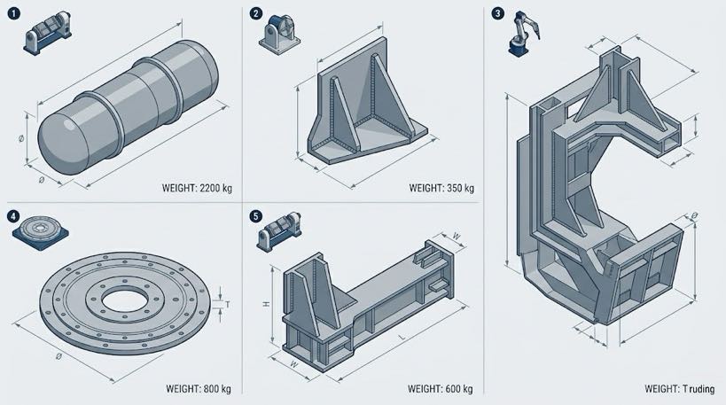
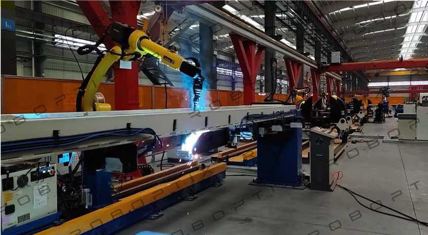
Not every Robot Positioner is the same, and not every large workpiece application calls for the same configuration. Three core Robot Positioner types address the specific challenges described above.
Configuration 1: Head-and-Tailstock Robot Positioner — Long Structural Components
The head-and-tailstock Robot Positioner supports a workpiece at both ends — one driven head, one passive tailstock — and rotates it along its primary axis. This is the correct configuration for long cylindrical or elongated structural components: pressure vessel shells, pipe spools, tower sections, heavy axle shafts, and similar geometries.
What it eliminates from the five root causes:
- Reason 1 (weight): Supports workpieces from 500 kg to 5,000 kg with precision servo drive — weight is no longer a repositioning constraint
- Reason 2 (posture): Continuously rotates the workpiece so the active weld joint is always presented in the flat or horizontal position
- Reason 3 (crane lifts): Eliminates mid-process crane repositioning entirely — the workpiece is loaded once and rotated as needed throughout the weld cycle
- Reason 5 (coordination): Reduces repositioning from a 4-person coordinated crane event to a single operator input
| Typical performance: On pressure vessel shell welding, head-and-tailstock Robot Positioner integration reduces repositioning time from 15–25 minutes per event to under 30 seconds. Arc-on time increases from 28–32% to 82–88% of shift hours. |
Configuration 2: U-Type Robot Positioner — Dual-Axis Control for Asymmetric Components
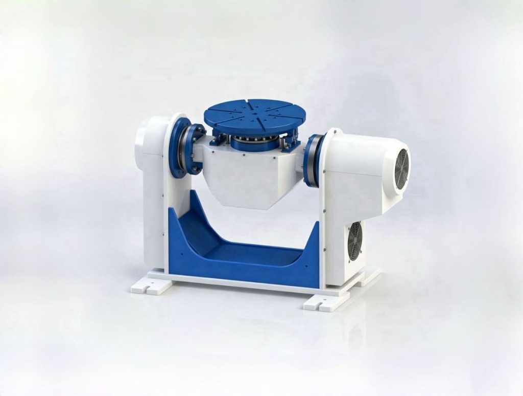
The U-type (dual-axis servo) Robot Positioner provides simultaneous tilt (J1 flip axis) and rotation (J2 rotation axis) control in a compact, high-rigidity frame. With a payload range of 300–1,000 kg, the U-type is designed for small-to-medium asymmetric components — welded brackets, automotive subframes, equipment housings, and similar parts where joints are distributed across multiple faces and a single rotation axis is insufficient.
Key design advantages for multi-face welding applications:
- Dual servo axes (J1 flip ±90°, J2 rotation ±200°) bring any joint face to the flat welding position within a single setup
- Compact footprint suitable for integration into automated welding cells with limited floor space
- Repeatability of ±0.05 mm (U001) to ±0.075 mm (U002) supports consistent weld joint presentation
- No crane or manual assistance required between face changes — both axes are servo-commanded
- Standard table diameters from 500 mm (U002) accommodate typical small-to-medium weldment sizes
What it eliminates from the five root causes:
- Reason 2 (posture): J1 flip axis tilts the workpiece so every joint face can be presented in the flat or horizontal welding position
- Reason 4 (access angle): Combined J1 + J2 motion brings any weld joint to the optimal angle without removing or re-fixturing the component
- Reason 5 (coordination): Both axis adjustments are programmed servo commands — no crane, no rigging, no multi-person coordination required
Configuration 3: Three-Axis Servo Robot Positioner — Heavy Complex Weldments
For components that combine high payload with weld joints distributed across multiple planes, the three-axis Robot Positioner (B008 / B009 / B010 / B011 series) provides coordinated rotation, tooling-axis rotation, and large-diameter swing capability. With payloads from 300 kg to 2,000 kg and maximum swing diameters up to 5,000 mm, this configuration handles the most geometrically demanding large weldments in heavy fabrication.
Typical application profile:
- Heavy structural frames with weld seams on 4+ faces (B011: 1,000–1,500 kg)
- Medium-complexity multi-face weldments in batch production (B009: 500–1,000 kg)
- Large-diameter components requiring wide swing clearance — up to 5,000 mm (B008)
- High-precision applications requiring ±0.03 mm rotation axis accuracy (B009, B011)
- Lighter complex geometry parts where access angle is the primary constraint (B010: 300–500 kg)
What it eliminates from the five root causes:
- Reason 4 (access angle): Independent rotation and tooling axes bring any joint on any face to flat or horizontal position without component removal
- Reason 2 (posture): The robot never welds out-of-position — the positioner handles all angle adjustments
- Reason 3 (crane lifts): The entire weld cycle completes within one setup; the crane is used only for load-in and load-out
Performance Comparison: Manual Repositioning vs. Robot Positioner
The following table reflects aggregated performance data from our installation records across large workpiece welding applications:
| Performance Metric | Manual Repositioning | Robot Positioner System |
| Average repositioning time per event | 15–25 minutes | ✅ 10–30 seconds |
| Arc-on time (% of shift hours) | ❌ 22–35% | ✅ 78–88% |
| Weld defect / rework rate | ❌ 8–15% | ✅ Below 1% |
| Crane lifts per component cycle | ❌ 4–8 lifts | ✅ 1 (load-in only) |
| Workers required per repositioning event | ❌ 3–4 people | ✅ 1 operator |
| Repositioning-related incident rate | ❌ Baseline | ✅ Reduced 80–90% |
| Shift capacity per station (large components) | ❌ 2–4 components | ✅ 5–8 components |
| Experienced welder physical demand | ❌ High — overhead/vertical | ✅ Low — flat/horizontal only |
How to Begin Your First Large Workpiece Automation Upgrade
The most common reason shops delay Robot Positioner adoption is not cost or technology — it is uncertainty about where to start. The following framework is the same assessment process we use with new customers before recommending any configuration.
Step 1: Characterize Your Workpiece Profile
Answer these four questions about the workpieces that cause the most production pain:
- Weight: What is the maximum component weight on your floor? (Determines positioner payload rating)
- Geometry: Is the component elongated/cylindrical, asymmetric/irregular, or multi-face complex? (Determines positioner type)
- Weld joint distribution: Are joints primarily on one axis, or distributed across multiple faces? (Determines axis requirements)
- Repositioning frequency: How many repositioning events does the current process require per component? (Determines efficiency gain potential)
Step 2: Identify Your Primary Pain Point
Use the root cause analysis from this article to identify which of the five inefficiency drivers is the biggest constraint on your specific operation:
| Primary Pain | Recommended Robot Positioner Starting Point |
| Repositioning time on long cylindrical / elongated parts | Head-and-Tailstock Robot Positioner — B001 (500–1,000 kg) / B002 (1,000–1,500 kg) / B004 (1,500–5,000 kg) |
| Multi-face access on small-to-medium asymmetric parts | U-Type Robot Positioner — U001 (300 kg) / U002 (500–1,000 kg) |
| Joint access on heavy multi-face complex geometry | Three-Axis Robot Positioner — B009/B011 (500–1,500 kg) / B008 (1,500–2,000 kg) |
| Horizontal rotation for medium-to-large disc / ring parts | H-Series Servo Rotation Table — H001–H005 (300–2,000 kg) |
| L-shaped dual-axis for welding + assembly positioning | L-Type Dual-Axis Robot Positioner — L001 (300–500 kg) / L002 (1,500 kg) |
Step 3: Calculate Your Current Repositioning Cost
Before requesting a quotation, quantify the problem you are solving. Use this simple framework:
- Count the average number of crane repositioning events per component
- Multiply by average event duration (include wait time, rigging, and clearance)
- Multiply by daily production cycles × annual working days
- Apply your loaded labor rate
The result is your annual repositioning cost baseline — the figure a Robot Positioner system will directly displace. In most large workpiece shops, this calculation produces a number that makes the investment case self-evident.
Step 4: Request an Application Assessment
A qualified Robot Positioner integrator should be able to review your workpiece drawings, current process data, and throughput targets and provide a written configuration recommendation with ROI projection within 24–48 hours. If the integrator cannot provide that level of application-specific analysis, they are not the right partner for a large workpiece application.
| Our free large workpiece assessment includes: • Review of your workpiece geometry and weight profile • Identification of your primary efficiency bottleneck(s) from the five root causes • Configuration recommendation (positioner type, payload, axis count) • Preliminary ROI projection based on your production data • Written report delivered within 24 business hours ► Contact us to schedule your assessment |
Coming Up in This Series
Article 3: Robot Positioner vs. Manual Welding Fixture — How to Choose the Right Solution for Your Factory
About the Author
| Experience & Expertise The author is a robotic welding system integration specialist with 12+ years of hands-on project experience, with a specific focus on Robot Positioner systems for heavy and large workpiece fabrication environments. The authoring company holds 26+ years of welding automation engineering experience, 40+ active patents, and has delivered 1,500+ completed projects across North America, Europe, and Asia — approximately 70% of which involve Robot Positioner integration with welding robots. Large workpiece applications (500 kg+) account for over 60% of the project portfolio. Certification: EU CE Certification for Robot Positioner systems (Certificate No.: M.2026.206.C134866) Research basis: Performance data cited in this article is sourced from on-site time-motion studies, post-installation audits, and production records across 300+ welding facilities in 15 countries. Last reviewed and updated: May 2026 |
RELATED POSTS
3D Vision Laser Seam Tracking Explained:From Point Cloud to Weld Path in Seconds
Robotic Welding Cell vs Manual Welding: Which Is Better for Modern Manufacturing?
7th Axis Robot Track System Maintenance & Troubleshooting Guide
Fixture-Free Fabrication: When a Welding Positioner Replaces Complex Jigs, Tack Welds, and Crane Time
Robot Positioner Payload Calculation and Safe Selection: The Complete Engineering Guide