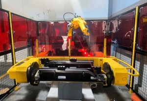
Custom Robot Workstations And Laser Systems Manufacturer


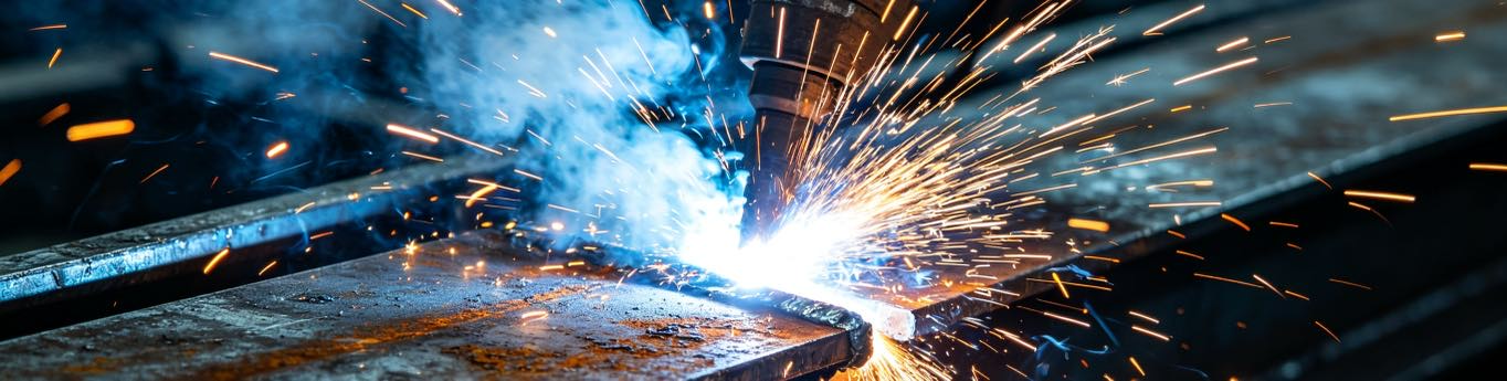
Round vs Rectangular vs Irregular: Matching Welding Positioner Configuration to Workpiece Geometry
Most buyers spec a welding positioner by industry: “I do pressure vessels,” or “I’m in structural steel.” Industry is a useful starting hint, not a selection rule. The real driver of welding positioner choice is geometry—the shape of the part and the path the weld must follow. A round pipe and a rectangular beam may both come from “heavy fabrication,” yet they demand completely different machines, and buying the wrong one is the difference between a cell that presents every weld flat and one that fights the part for eight hours a day. This article classifies weldments into three geometries—round, rectangular, and irregular—and matches each to the welding positioner configuration that holds the weld in the flat or horizontal band (1G/2G) with the least drama and the best repeatability.
The payoff of getting geometry right is consistency. Hold the weld in the flat/horizontal position and you hold a near-constant gravity vector at the pool—the single biggest determinant of puddle stability. Peer-reviewed work shows pool behavior and bead quality vary sharply with welding position (Park et al., 2019; Liu et al., 2023). Choosing the welding positioner that keeps your specific shape in that stable band is how you turn that research into a cell design rule, and it is also how you avoid paying for capability you do not need.
Note: Configuration guidance reflects ROBOPTIX welding positioner deployments across pipe, structural, and complex-weldment fabrication, cross-referenced with peer-reviewed position-dependent pool-behavior research (Park et al., 2019; Liu et al., 2023) and ISO 9283 multi-axis accuracy .
1. Why Geometry, Not Industry, Should Drive the Choice
Two fabricators in the same industry can need opposite welding positioners. One pressure-vessel shop welds long circumferential seams on cylinders—pure rotation, the simplest case in the book. Another welds nozzles, saddles, and manways onto those same vessels—irregular, multi-orientation work that needs continuous reorientation. “Pressure vessel” names the sector; the part’s geometry names the machine. Start every selection from the weldment shape and the seam path, then let industry refine the details: the welding code (ASME Sec. VIII versus AWS D1.1 change fixture and access needs), the throughput target, and the duty cycle. A structural shop doing one-off heavy frames and a structural shop doing repeated trailer beams may also land on different positioners despite sharing the same label—because their parts are different shapes, not because their industry is.
2. Round Workpieces: Pipes, Tanks, and Rotational Seams
Round parts—pipes, tubes, pressure-vessel shells, wind-tower sections, rotors—share one structural gift: a circumferential seam can be welded at a single, fixed torch position while the part rotates beneath it. The weld sits at 12 o’clock in the flat position (1G) for the entire pass. This is the cleanest, most repeatable case in all of welding positioner work, because nothing about the weld orientation changes as the part turns—gravity, torch angle, and travel direction are all constant, which is exactly the condition research ties to stable pools.
2.1 Best Configuration: Turning Rolls, Headstock-Tailstock, Rotary Tables
- Turning rolls: For large-diameter, thin-wall cylinders (tanks, wind towers, big-bore pipe), powered drive rolls plus idler rolls rotate the shell. Nothing grips the part, so distortion is minimal and the seam rides the top. Ideal when the part is too large or too delicate to chuck, and when you want a welding positioner that handles a family of diameters rather than one fixed chuck size. Size the drive-roll torque for the part mass and the required rotation speed; under-powered rolls slip and the seam speed varies, which shows up as uneven penetration.
- Headstock-tailstock: For pipes, tubes, and shafts, a driven chuck (headstock) plus a support tailstock rotates the part between centers. The ROBOPTIX B001–B004 series fits here. Best when you need precise angular indexing between passes (for example, a circumferential root, then fill passes stepped around the joint) and positive, slip-free drive. The tailstock is not optional for long parts—it carries the overhang that would otherwise cantilever the pipe.
- Rotary table: For shorter cylindrical parts, a rotary positioner (rotate about a vertical or horizontal axis) gives simple, accurate circumferential welding without a full head-tail frame. A vertical-axis rotary table is also the natural choice when the round part must be loaded from above by a crane or a robot.
2.2 Watch-Outs: Long Cantilevered Pipe, Thin-Wall Distortion
Two failure modes dominate round-part work. First, a long pipe rotated from one end only becomes a cantilever—the far end sags and the seam drifts off target (the overturning logic from P05). Always support long spans with a tailstock or a second roll set; as a practical rule, support the part wherever its unsupported length would let it deflect more than your seam-tracking tolerance. Second, thin-wall shells distort under the heat line—weld shrinkage pulls the joint out of flat as you go. Control rotation speed for steady heat input, and use seam tracking so the torch follows the moving joint rather than a fixed point in space. Round is the easy geometry, but only when the span is supported and the wall is tracked.
3. Rectangular Workpieces: Structural Steel and Frames
Rectangular parts—beams, frames, plates, box sections—have no clean rotation axis, so you cannot simply spin them the way you spin a pipe. Instead you tilt and flip them to bring each weld into the flat or horizontal band, then index to the next joint. The welding positioner’s job here is reorientation, not continuous rotation, and the value is in how many faces it can present without a crane re-set. Every flip the positioner makes is a crane lift you do not pay for, and on a long frame those lifts add up to real hours.
3.1 Best Configuration: L-Type, H-Type, Tilt-Rotate Tables
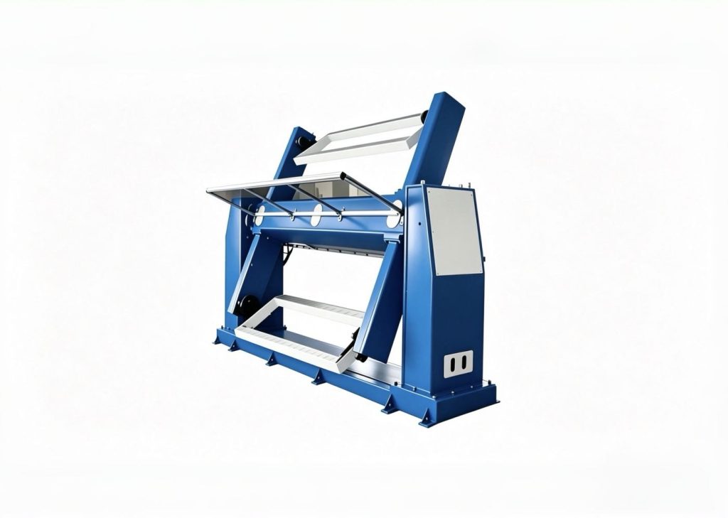
- L-type positioner: A tilt axis plus a rotate (slew) axis flips a beam or frame so any face presents flat. It is the workhorse for structural steel; ROBOPTIX L-type units handle asymmetric frames that a plain rotary table physically cannot, because the tilt axis carries the part’s weight while the rotate axis indexes it to the next weld.
- H-type / dual: Two synchronized tilt-rotate units cradle a long member at both ends, sharing the load and the overturning moment (Eccentric Load & Overturning Moment: Why a 2-Ton Welding Positioner Fails a 2-Ton Part) across two axes—essential for long, heavy sections where one unit would be overloaded or would twist the part. Synchronization matters: the two tilt axes must move as one or the beam racks and the seams shift.
- Turntable + tilt: For plate and panel work, a tilting turntable presents large flat areas efficiently and is simple to load with an overhead crane. It is the pragmatic choice when the parts are wide and thin and the seams are mostly straight runs across a face.
3.2 Watch-Outs: Asymmetric Load, Multi-Station Indexing
Rectangular parts are usually asymmetric, so their center of gravity sits off the rotation axis—exactly the condition that shrinks real capacity (Eccentric Load & Overturning Moment: Why a 2-Ton Welding Positioner Fails a 2-Ton Part). Size the tilt axis on overturning moment, not on mass: a 2,000 kg frame whose CoG sits 0.5 m off the tilt axis presents a 1,000 kg·m moment, and that moment—not the 2,000 kg—is what the positioner must hold without sagging. Long frames also demand multi-station indexing: plan the welding positioner path so every weld is reachable in the flat position without lifting the part off to re-fixture. The L-type earns its keep by eliminating those crane resets, and the time saved is often the real return on the purchase.
4. Irregular Workpieces: Castings, Weldments, Mixed Shapes
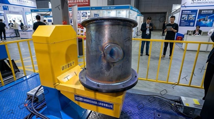
Irregular parts—castings, complex fabricated weldments, mixed contours—carry seams that change orientation along their length. No single tilt-and-rotate setting holds them all flat. You need continuous, programmable reorientation: the welding positioner must effectively “follow” the weld, reorienting the part as the torch advances. This is the hardest tier, and also where the positioner and the robot stop being separate machines (Coordinated Motion Programming: Robot and Positioner as One Kinematic Chain).
4.1 Best Configuration: 3-Axis Servo, Robot-Coordinated Positioners
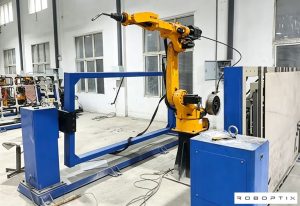
- 3-axis servo positioner: Tilt + rotate + a linear or secondary rotate axis lets the controller orient almost any contour. The ROBOPTIX B008–B012 multi-axis servo units fit here, with the accuracy to hold orientation through complex paths (verified per ISO 9283). Three axes are usually the minimum to keep a genuinely 3D seam in the flat band as it travels.
- Robot-coordinated positioner: Declare the positioner as an external axis in the robot controller so both move as one kinematic chain ( Coordinated Motion Programming: Robot and Positioner as One Kinematic Chain). The robot tracks the seam while the positioner keeps it oriented—the only practical way to weld truly 3D contours at production quality, with constant tool-center-point speed and no cold-restart defects. This is where the earlier articles converge: coordination and verification (Coordinated Motion Programming: Robot and Positioner as One Kinematic Chain) are what make an irregular-part cell actually work in production.
4.2 Watch-Outs: Changing CoG, Singularity Avoidance
As an irregular part rotates, its center of gravity moves, so the load on each axis changes through the cycle—verify capacity at the worst angle, not the average (Eccentric Load & Overturning Moment: Why a 2-Ton Welding Positioner Fails a 2-Ton Part), because the positioner may be fine at one orientation and overloaded at another. Multi-axis units also reach singular orientations where they lose mechanical authority; plan paths to avoid them, or add a redundant axis. Program complexity and calibration cost rise with axis count, so reserve this tier for parts that genuinely need it rather than for work a simpler machine would handle—an L-type that flips a near-rectangular casting may be cheaper and just as good.
5. Decision Framework: Geometry → Configuration
Use the table below as a first filter, not a verdict. Many real parts are hybrids—a rectangular frame with round bosses, a tank with irregular nozzles—and the right answer is often the higher tier. When in doubt, size for the hardest seam, not the average one, and remember that a more capable welding positioner also covers your future work, which is a real asset when orders are uncertain.
| Workpiece geometry | Recommended positioner | Why it works | Primary watch-out |
| Round / cylindrical (pipes, tanks, shells) | Turning rolls or headstock-tailstock | Seam stays at top in flat (1G) with simple rotation | Support long spans; thin-wall distortion |
| Rectangular / plate (beams, frames) | L-type or H-type tilt-rotate | Flip/tilt to present each face flat | Asymmetric CoG → overturning moment |
| Irregular / 3D (castings, mixed) | 3-axis servo or robot-coordinated | Continuous reorientation follows the seam | Changing CoG; singularity; program cost |
6. How to Define Your Geometry (a Practical Step for Buyers)
This is the step where selection goes wrong most often: buyers describe parts by name—“a bracket,” “a manifold”—instead of by geometry and seam path. Before you ask a supplier for a welding positioner, characterize three things. First, the dominant shape: does the seam run around a rotation axis (round), across faces you must flip (rectangular), or along a contour that never sits still (irregular)? Second, the seam length and how many orientations it passes through; a seam that stays in one band is rectangular-simple, one that rotates through three is irregular. Third, the part mass and its center of gravity at each weld, because that drives the load rules (Eccentric Load & Overturning Moment: Why a 2-Ton Welding Positioner Fails a 2-Ton Part). Write this down as a one-page part profile and the configuration choice usually makes itself—and you can hand the same profile to three suppliers and finally compare like for like, instead of comparing three different assumptions.
7. How Geometry Meets the Load and Accuracy Rules
Geometry choice and the earlier rules in this series are the same decision seen from two sides. A round part on turning rolls is easy on the welding positioner precisely because it keeps the weld in the flat position and the load symmetric—low overturning moment (Eccentric Load & Overturning Moment: Why a 2-Ton Welding Positioner Fails a 2-Ton Part) and simple, repeatable motion that is cheap to verify . An irregular part on a 3-axis servo is hard because it fights both: a moving center of gravity loads the axes unevenly, and continuous reorientation demands tight, verified accuracy (Can You Trust the Spec Sheet? Verifying Welding Positioner Accuracy with Laser Trackers and ISO 9283) from a multi-axis unit. Choosing geometry first is how you keep those other constraints manageable instead of discovering them after commissioning, when changing the machine is no longer an option and the cost is a line you cannot un-buy.
8. Field Example: One Cell, Three Geometries
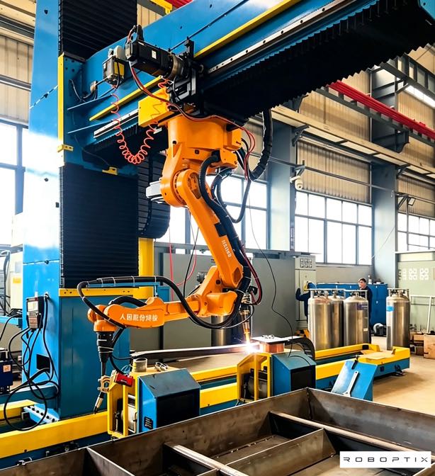
A ROBOPTIX customer built three product families on one floor: pipe spools (round), trailer frames (rectangular), and pump housings (irregular). They initially ran all three on a single L-type positioner—the only machine they owned. The pipe spools welded poorly: the L-type flipped them instead of rotating them, leaving circumferential seams in awkward, partly overhead positions with cold-restart defects and a first-pass yield in the low 80s. The frames were acceptable, and the housings were worst of all, needing constant manual repositioning. Reconfiguring to a headstock-tailstock for the spools, keeping the L-type for frames, and adding a 3-axis servo cell for the housings lifted first-pass yield across all three from the low 80s to above 95%, and cut handling time roughly in half. The parts never changed; the geometry match did. One floor, three geometries, three correct welding positioners—and a clear lesson that the shape, not the sector, decides the cell.
9. When Geometry Doesn’t Decide
Geometry is the first filter, not the only one. Throughput, floor space, budget, and robot compatibility often override a textbook match. A small shop welding mostly rectangular frames may still buy a versatile 3-axis servo because it covers every geometry and future work—paying more for flexibility than for the “perfect” single-geometry machine, and that flexibility is a rational hedge against uncertain orders. And very simple round or rectangular parts at loose tolerance may not need a precision servo at all; a basic welding positioner presents them flat well enough. Use geometry to narrow the field, then let cost, capacity, and compatibility close the decision. The worst outcome is buying the wrong tier for the right reason—over-specifying because a brochure scared you, or under-specifying because you saved a line item that later cost you a cell.
Frequently Asked Questions
Q: How do I choose a welding positioner for pipes and round tanks?
A: Use rotation, not flipping. Turning rolls suit large thin-wall cylinders such as tanks and wind towers; a headstock-tailstock (driven chuck plus tailstock) suits pipes, tubes, and shafts needing precise indexing. Both keep the circumferential seam at the top in the flat position while the part rotates, and both avoid the crane resets a flip-based positioner would require for a round seam.
Q: What welding positioner is best for structural steel beams and frames?
A: An L-type (tilt + rotate) positioner flips and presents each face flat; long or heavy members benefit from an H-type pair sharing the load. Size the tilt axis on overturning moment, because rectangular parts are usually asymmetric and off-center, and the center of gravity—not the mass—is what the axis must hold without sagging.
Q: When do I need a 3-axis or robot-coordinated welding positioner?
A: When the seam changes orientation along the part—castings, complex weldments, mixed 3D contours—and no single tilt-rotate setting holds it flat. A 3-axis servo or a positioner declared as a robot external axis keeps reorienting the weld continuously as the torch advances, which is the only practical route to quality on truly 3D seams.
Q: Can one welding positioner handle all three geometries?
A: A 3-axis servo or robot-coordinated unit can, because it covers the orientation range of the simpler types. But it costs more and is overkill for high-volume round or rectangular work where a dedicated machine is faster and cheaper. Match the welding positioner to your dominant geometry; add versatility only where you truly need it, or where future orders are uncertain.
Industry tells you the sector; geometry tells you the machine. Round parts want rotation—turning rolls or headstock-tailstock—so the circumferential seam stays flat while the part turns. Rectangular parts want reorientation—L-type or H-type tilt-rotate—to flip each weld into the flat band. Irregular parts want continuous, programmable orientation—3-axis servo or robot-coordinated—to follow a seam that never sits still. Match the configuration to the shape and you present every weld in the gravity-stable flat/horizontal position that research ties to better pools (Park, 2019; Liu, 2023).
ROBOPTIX covers all three tiers—B001–B004 head-tail and turning-roll systems for round work, L-type and H-type units for rectangular frames, and B008–B012 multi-axis servo welding positioners for irregular and robot-coordinated cells—so the geometry match is a catalog decision, not a compromise. Write a one-page part profile, match it to the framework above, and the welding positioner you specify will be the one you actually weld with. The next article (P09) turns from matching the machine to auditing the supplier: a factory-visit checklist and bench-test protocol for buyers who want to verify the vendor the same way they verify the machine.
Not sure which tier fits your part?
Send ROBOPTIX your weldment drawing and seam path—we will match geometry to configuration and size the load for you.
About the Author
Experience & Credentials
Robotic welding system integration specialist with 12+ years of direct project experience focused on Robot Positioner selection and integration. Has provided consulting to 300+ factories across North America, Europe, and Asia. All specification data in this article is drawn from actual H / B / L / U series product datasheets.
Company background: 26+ years of welding automation engineering, 40+ active patents, 1,500+ completed projects globally, approximately 70% involving Robot Positioner integration.
Certifications
- ISO 9001: 2015 (GB/T 19001-2016) — Quality Management System
- GJB 9001C-2017 — Military/Weapon Equipment Quality Management System
- EU CE — Machinery Directive 2006/42/EC (Cert. No. M.2026.206.C134866)
- High-Tech Enterprise — Cert. No. GR202341000595 (Issued Nov. 2023)
Last updated: Jun 2026
References
[1] Park, J.-H., Kim, S.-H., Moon, H.-S., & Kim, M.-H. (2019). Influence of Gravity on Molten Pool Behavior and Analysis of Microstructure on Various Welding Positions in Pulsed Gas Metal Arc Welding. Applied Sciences, 9(21).
[2] Liu, J., Jiang, F., Chen, S., Xu, B., Zhang, G., Cheng, W., & Ma, X. (2023). Mechanisms of Gravitational Influence on Weld Pool Behavior and Weld Bead Performance in Variable Polarity Plasma Arc Welding across Different Welding Position. Materials, 16(19).
[3] International Organization for Standardization. (1998). ISO 9283:1998, Manipulating Industrial Robots — Performance Criteria and Related Test Methods.
RELATED POSTS
6 Common Challenges in Robotic Laser Welding and How to Solve Them
Robotic Laser Welding: Principles, Advantages, and Applications (2026 Complete Guide)

Real-World Robotic Welding Cell Applications in General Industry: Case Studies 2026
5 Questions to Ask Before Buying a Robotic Welding Cell for Structural Steel
Can You Trust the Spec Sheet? How to Verify Welding Positioner Accuracy with Laser Trackers and ISO 9283