Custom Robot Workstations And Laser Systems Manufacturer


2026 Robot Positioner Buyer’s Guide: All 5 Types Compared — Head-and-Tailstock, L-Type, U-Type, and More
The Wrong Robot Positioner Costs More Than No Robot Positioner
A production manager at an engineering machinery plant once told me they chose a head-and-tailstock Robot Positioner on their first purchase purely because it was the lowest-priced option. Three months later, 90% of their workpieces turned out to be irregular multi-face structures the head-and-tailstock could not handle. The unit sat idle while workers still repositioned everything by hand. Returning it, re-purchasing, and reprogramming added 65% on top of the original budget.
There is no universally superior Robot Positioner — only the right one for your workpiece. This article compares all five mainstream types by structure, specifications, and real application fit, so you can make the right decision before you buy.
| How to use this article: This is the core reference page for Robot Positioner selection. If you already know your workpiece type, jump directly to that section. For a fast overview, start with the summary table below. |
All 5 Types at a Glance
Before examining each type in depth, use this table to orient yourself:
| Type | Axes | Workpiece Fit | Payload Range | Typical Accuracy | Relative Cost |
| Head-and-Tailstock (B Series) | 1 | Long, tubular, axially symmetric | 500–5,000 kg | 0.05 mm | Mid |
| H-Type Rotation Table (H Series) | 1 | Disc, ring, planar | 300–2,000 kg | ±0.05 mm | Low |
| L-Type Dual-Axis (L Series) | 2 | Mid-size multi-face; weld + assembly | 300–1,500 kg | ±0.05 mm | Mid |
| U-Type Dual-Axis (U Series) | 2 | Small to mid-size multi-face | 300–1,000 kg | ±0.05 mm | Mid |
| Three-Axis (B008–B012) | 3 | Complex, heavy, multi-face | 300–2,000 kg | ±0.03 mm+ | High |
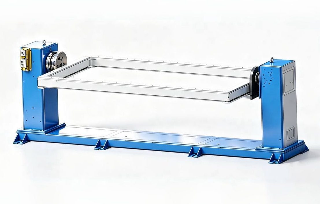
Type 1: Head-and-Tailstock Robot Positioner (B Series)
What workpieces does it suit?
Pressure vessel shells, wind turbine tower sections, large drive shafts, engineering machinery boom bodies, pipe manifolds. The defining characteristic: the workpiece is elongated or axially symmetric, and both ends can be gripped concentrically.
How it works
A servo-driven head grips one end; a passive tailstock supports the other. The workpiece rotates continuously along its primary axis while the welding robot tracks along the length. Circumferential seams are welded entirely in the flat position, pushing arc-on time to 85% or higher.
Actual model specifications
| Model | Rated Payload | Positioning Accuracy | Max Flip Speed | Standard Span |
| MRK-B001 (Light) | 500–1,000 kg | 0.05 mm@R350 | 90°/s | 2 / 2.5 / 3 / 3.5 m |
| MRK-B002 (High-Load) | 1,000–1,500 kg | 0.05 mm@R350 | 60°/s | 2 / 2.5 / 3 / 3.5 m |
| MRK-B004 (Heavy-Duty) | 1,500–5,000 kg | ±0.075 mm@R500 | 30°/s | 3 / 5 / 6 / 8 m |
Strengths and limitations
- Strengths: Highest payload ceiling of all five types (B004: 5,000 kg); maximum arc-on time on circumferential seams; simplest mechanical design and lowest maintenance cost
- Limitations: Only suitable for axially symmetric or elongated workpieces; cannot handle multi-face irregular parts; both ends of the workpiece must be concentric and grippable
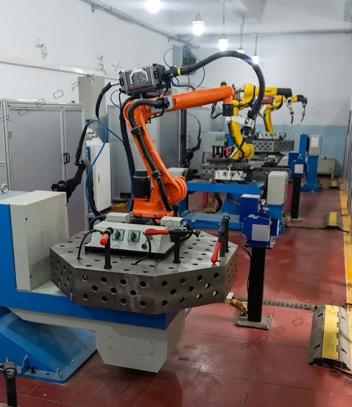
Type 2: H-Type Servo Rotation Table (H Series)

(Robot is not included)
What workpieces does it suit?
Flanges, circular structural frames, EV battery pack trays, circular end caps, ring sections. The defining characteristic: disc-shaped, ring-shaped, or planar geometry with a low height-to-diameter ratio.
How it works
A circular table rotates around a vertical axis. The workpiece is fixed to the table and rotates to each target angle while the welding robot completes seams sequentially. Simplest structure of all five types, lowest integration cost, easiest to commission.
Actual model specifications
| Model | Rated Payload | Positioning Accuracy | Max Speed | Standard Table Dia. / Max Swing Dia. |
| MRK-H001 | 500–2,000 kg | ±0.05@R350 | 60°/s | 600–2,000 mm / multiple options |
| MRK-H004 (Standard) | 500–1,500 kg | ±0.05 mm@R350 | 60°/s | 1,500 mm / 2,000 mm |
| MRK-H005 (Heavy) | 1,500–2,000 kg | ±0.05 mm@R350 | 45°/s | 2,500 mm / 3,000 mm |
Strengths and limitations
- Strengths: Lowest cost and simplest integration of all five types; large table surface for flexible workpiece fixturing; wide table diameter range (600 mm to 2,500 mm)
- Limitations: Horizontal rotation only — side-face and bottom-face weld seams are inaccessible; stability degrades when workpiece height-to-diameter ratio exceeds 0.8
Type 3: L-Type Dual-Axis Robot Positioner (L Series)
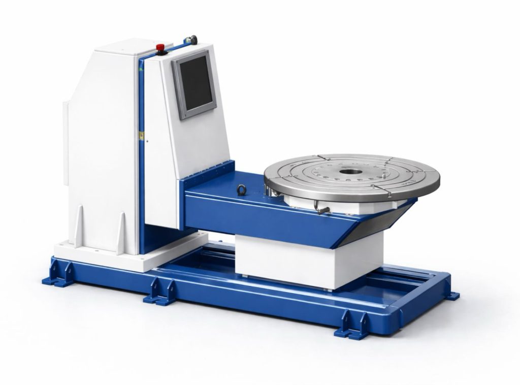
What workpieces does it suit?
EV battery pack frames, motorcycle and bicycle frames, aluminum structural weldments, mid-size workpieces that require welding and assembly operations at the same station. The defining characteristic: multi-face welding combined with an assembly step at the same fixture.
How it works
An L-shaped frame combines two independent servo axes: a tooling axis (horizontal rotation) to orient the workpiece, and a flip axis to adjust tilt. Two-axis coordination covers 4 to 6 weld faces in a single setup. The tooling axis also doubles as an assembly indexing reference, enabling welding and parts assembly at the same station without any workpiece transfer.
Actual model specifications
| Model | Rated Payload | Tooling Axis Accuracy | Flip Axis Accuracy | Tooling Axis Speed |
| MRK-L001 (Light Dual-Axis) | 300–500 kg | ±0.05 mm@R350 | ±0.075 mm@R500 | 60°/s, accel 45°/s² |
| MRK-L002 (Heavy Dual-Axis) | 1,500 kg | Rotation torque: 3,960 N·m | Flip torque: 6,720 N·m | Rotation 4 rpm / Flip 3 rpm |
Strengths and limitations
- Strengths: The only type that natively supports combined welding and assembly at one station; L002 heavy-duty torque handles 1,500 kg aluminum frames; dual-axis covers multiple faces in a single setup
- Limitations: For pure welding applications without assembly requirements, a U-type typically offers better cost efficiency; flip range is limited — applications requiring >90° flip are not well suited
Type 4: U-Type Dual-Axis Robot Positioner (U Series)
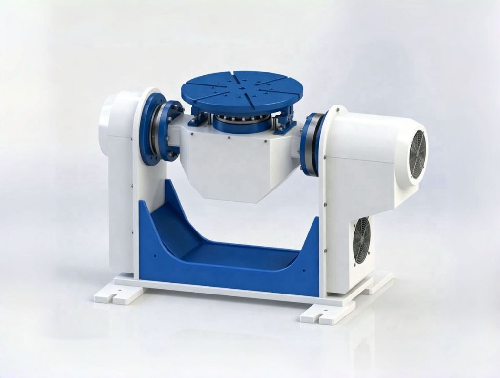
What workpieces does it suit?
Automotive structural brackets, instrument panel frames, body-in-white weldments, standard robotic welding cell components. The defining characteristic: multi-face geometry, 300 to 1,000 kg, high-volume production with strict consistency requirements.
How it works
A U-shaped frame houses a J1 flip axis (±90°) and J2 rotation axis (±200°) in coordinated servo motion. Any face of the workpiece can be brought to the flat-welding position without removing the part from the fixture. Compact footprint (~1.2 m²) and fast axis response make this the dominant choice for automotive parts batch welding.
Actual model specifications
| Model | Rated Payload | Repeatability | J1 Flip Speed | J2 Rotation Speed |
| MRK-U001 (Light) | 300 kg | ±0.05 mm@R250 | 30°/s, torque 2,695 N·m | 60°/s, torque 1,225 N·m |
| MRK-U002 (Standard) | 500–1,000 kg | Flip: ±0.075 mm@R500 Tool: ±0.05 mm@R350 | 45°/s | 60°/s, accel 45°/s² |
Strengths and limitations
- Strengths: Completely eliminates overhead and vertical welding; U001 achieves ±0.05 mm@R250 for automotive precision requirements; smallest footprint of all dual-axis types — multiple units can be deployed side by side
- Limitations: Payload ceiling of 1,000 kg (U002) rules it out for heavy workpieces; J1 flip range of ±90° is insufficient for rare applications requiring greater tilt
Type 5: Three-Axis Robot Positioner (B008–B012 Series)
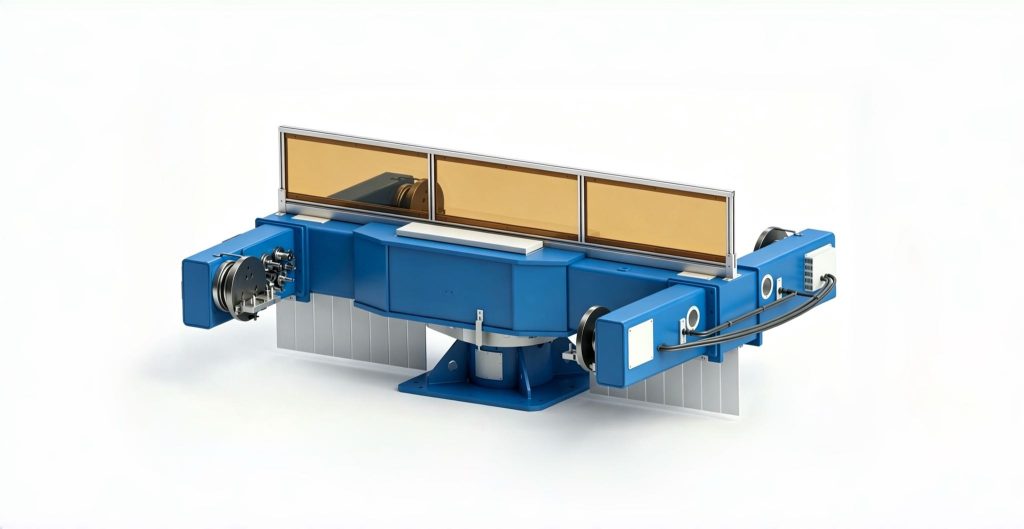
What workpieces does it suit?
Excavator boom arms and dippers, crane jib sections, wind turbine nacelle frames, mining equipment main structures. The defining characteristic: weld seams distributed across 6 or more planes, complex geometry, 500 kg and above.
How it works
Three coordinated servo axes — a large-swing rotation axis, a tooling axis, and a flip control — bring any weld seam on any face to flat-welding position in sequence, eliminating crane repositioning mid-cycle. B008 reaches a maximum swing diameter of 5,000 mm; high-accuracy models B009 and B011 achieve ±0.03 mm repeatability.
Actual model specifications
| Model | Rated Payload | Rotation Accuracy | Max Swing Dia. | Tooling Accuracy | Tooling Speed |
| MRK-B008 (Heavy) | 1,500–2,000 kg | ±0.05 mm@R500 | 5,000 mm | ±0.05 mm@R350 | 60°/s |
| MRK-B009 (Modular) | 500–1,000 kg | ±0.03 mm@R500 | 4,000 mm | ±0.05 mm@R350 | 90°/s |
| MRK-B010 (Light) | 300–500 kg | ±0.075 mm@R500 | 4,000 mm | ±0.075 mm@R500 | 60°/s |
| MRK-B011 (Standard) | 1,000–1,500 kg | ±0.03 mm@R500 | 4,000 mm | ±0.05 mm@R350 | 90°/s |
| MRK-B012 (Vertical Flip) | 300–1,500 kg | ±0.075 mm@R500 | — | ±0.05@R350 | 60°/s |
Strengths and limitations
- Strengths: Broadest workpiece adaptability of all five types; highest precision available at ±0.03 mm; eliminates all crane repositioning mid-cycle
- Limitations: Highest purchase cost and most complex integration; payload ceiling of 2,000 kg — workpieces above this require a heavy-duty head-and-tailstock (B004: 5,000 kg)
Side-by-Side Comparison: All 5 Types
| Dimension | Head-and-Tailstock (B) | H-Type (H) | L-Type (L) | U-Type (U) | Three-Axis (B008–B012) |
| Workpiece adaptability | ❌ Axially symmetric only | ❌ Disc / planar only | ✅ Moderate | ✅ Broad | ✅ Widest |
| Maximum payload | ✅ 5,000 kg | ✅ 2,000 kg | ⚪ 1,500 kg | ❌ 1,000 kg | ⚪ 2,000 kg |
| Eliminates overhead welding | ⚪ Circumferential seams only | ❌ Top face only | ✅ Multi-face effective | ✅ All faces eliminated | ✅ All faces eliminated |
| Assembly function support | ❌ No | ❌ No | ✅ Tooling axis dual-purpose | ❌ No | ❌ No |
| Floor space required | ❌ Large (span 2–8 m) | ✅ Small | ⚪ Medium | ✅ Smallest | ⚪ Medium |
| Integration complexity | ✅ Low | ✅ Lowest | ⚪ Medium | ⚪ Medium | ❌ High |
| Purchase cost | ⚪ Mid | ✅ Lowest | ⚪ Mid | ⚪ Mid | ❌ Highest |
⚪ = Middle range / between the two extremes
4-Step Selection Process
Step 1: Identify your workpiece geometry
- Elongated or tubular workpiece, both ends grippable → Head-and-Tailstock
- Disc, ring, or planar geometry → H-Type Rotation Table
- Multi-face, 300–1,000 kg, pure welding → U-Type
- Multi-face with welding + assembly at same station → L-Type
- Weld seams on 6+ planes, complex geometry → Three-Axis
Step 2: Verify your load — workpiece + fixture, with 20% margin
Selection load = (workpiece weight + fixture weight) × 1.2. Using only the workpiece net weight is the single most common selection error. Fixtures routinely add 15–30% to the total load — ignoring them causes chronic overloading and premature drivetrain failure.
Step 3: Match the accuracy requirement
- General structural welding: ±0.05 mm is fully sufficient
- Automotive precision components: ±0.05 mm (U001) or ±0.03 mm (B009/B011)
- Heavy structural fabrication with coarse tolerances: ±0.075 mm is acceptable (B004, B010)
Step 4: Choose your control integration mode
- Coordinated axis control (recommended): The Robot Positioner operates as an external axis of the welding robot. Rotation and welding occur simultaneously in real-time synchronization — arc-on time is maximized
- Independent control: Welding and rotation alternate. Lower integration cost, but arc-on time cannot be fully optimized — appropriate for simple processes or tight budgets
3 Most Common Selection Mistakes
| Mistake 1: Buying the largest payload rating for safety margin. → Oversized payload means greater rotational inertia, slower response, and unnecessary cost. Select based on actual load × 1.2, not the largest available model. |
| Mistake 2: Assuming more axes is always better. → A three-axis unit costs 2–3× a single-axis unit and requires significantly longer commissioning. If your workpieces have only circumferential seams, a single-axis head-and-tailstock is the optimal solution. |
| Mistake 3: Planning to start cheap and upgrade later. → Different Robot Positioner types have incompatible fixture mounting patterns and control architectures. Upgrading means redesigning fixtures and reprogramming from scratch. Getting it right the first time is almost always less expensive than switching. |
Get a Free Selection Assessment
If your workpiece situation is complex or you are still uncertain about the right configuration, our engineering team provides free application assessments — specific model recommendation, span or table size, and a preliminary ROI estimate — delivered in writing within 24 business hours.
► Contact us for a free Robot Positioner selection assessment
About the Author
| Experience & Credentials Robotic welding system integration specialist with 12+ years of direct project experience focused on Robot Positioner selection and integration. Has provided consulting to 300+ factories across North America, Europe, and Asia. All specification data in this article is drawn from actual H / B / L / U series product datasheets. Company background: 26+ years of welding automation engineering, 40+ active patents, 1,500+ completed projects globally, approximately 70% involving Robot Positioner integration. EU CE Certification: Robot Positioner systems (Certificate No.: M.2026.206.C134866) Last updated: May 2026 |
RELATED POSTS
Installation & Maintenance Guide for Robotic Laser Welding Systems: A Practical Roadmap
10 Key Benefits of Implementing a Robotic Welding Cell in Your Shop
What Is a Robotic Welding Cell? 2026 Beginner’s Guide | 37 Shop Data
How to Calculate Robotic Welding Cell ROI in 2026: Complete Template with Real-World Cases
7th Axis Robot + Robotic Positioners: Building Complete Flexible Welding Cells