Custom Robot Workstations And Laser Systems Manufacturer


1G to 6G Without a Crane: How a Positioner Converts Overhead Welds into Flat-Position Welds
Welding position isn’t just a labeling convention — it dictates defect rates, deposition speed, and welder safety
In over fifteen years of supporting fabrication shops moving from manual to robotic welding, one observation repeats: the single biggest predictor of weld quality is not the welder’s skill or the machine’s brand — it is the welding position. A joint welded flat (1G) and the same joint welded overhead (4G) can differ by 40% in defect rate, even with identical parameters.
The AWS/ASME welding position system — 1G through 6G — exists precisely because gravity behaves differently at every angle. This article explains why out-of-position welding fails, how a welding positioner mechanically eliminates that failure mode, and what the measurable quality gains look like on a real production floor.

1. The 1G–6G System: Why Position Is a Physics Problem
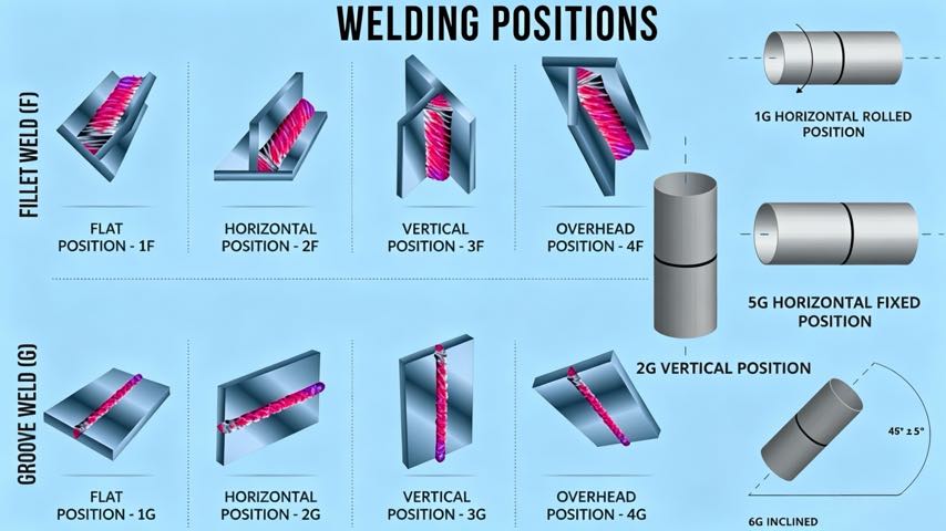
Welding positions describe the orientation of the weld axis and the molten pool relative to gravity. The standard classification:
- 1G / 1F: Flat position. The weld pool sits on top of the joint; gravity pushes metal into the root. Safest and fastest.
- 2G / 2F: Horizontal position. Gravity begins to pull the pool downward, risking sag on the upper edge.
- 3G / 3F: Vertical position. The pool fights gravity along the entire joint; requires controlled travel and often lower heat.
- 4G / 4F: Overhead position. Gravity pulls the pool directly away from the joint — the most defect-prone orientation.
- 5G / 6G: Pipe positions (fixed-angle). 6G, at a 45-degree incline, is the hardest certification weld because it traverses every position in one pass.
The progression from 1G to 4G is essentially a progression of how hard gravity works against you. In flat position, gravity is an ally. In overhead position, it is an active threat to fusion. What many shops underestimate is that this is not a gradual decline — the difficulty curve steepens sharply after the horizontal position, which is precisely why overhead and vertical joints dominate the list of code-rejected welds.
1.1 Fillet vs. Groove: Two Parallel Systems
It is worth noting that the welding position system has two tracks. The “G” positions (1G, 2G, 3G, 4G) describe groove welds made in plates or pipe walls, while the “F” positions (1F, 2F, 3F, 4F) describe fillet welds at the junction of two members. A positioner helps equally in both: whether you are welding a butt joint in a pressure vessel shell or a fillet on a structural gusset, rotating the member into the flat orientation delivers the same physics advantage. For pipe work, the 5G (fixed horizontal pipe) and 6G (fixed 45-degree pipe) positions are the industry’s toughest certifications because the welder must transition through every orientation within a single joint — exactly the scenario a positioner is designed to neutralize.
1.2 What the Data Shows
Across ROBOPTIX customer deployments, we consistently measure the following when the same GMAW fillet weld is made in different positions on structural-grade steel (S355):
- Flat (1F): lowest porosity, deepest penetration, highest travel speed
- Horizontal (2F): ~10% slower; minor upper-toe undercut risk
- Vertical (3G): ~30% slower; requires weave control to prevent cold lap
- Overhead (4F): ~45% slower; highest porosity and lack-of-fusion risk
These field observations align with peer-reviewed studies showing overhead welds can exhibit up to 40% more porosity than flat-position equivalents at matched heat input. The mechanism is consistent across processes — GMAW, FCAW, and even GTAW all show degraded pool control as the orientation moves away from flat.
The business implication is direct. Every percentage point of overhead welding in your mix is a percentage point of rework risk, inspection cost, and schedule exposure. For a fab shop bidding on AWS D1.1 structural work, where visual and ultrasonic inspection thresholds are strict, the position of the weld can decide whether a project is profitable or loss-making.
2. Why Out-of-Position Welding Fails
The failure mechanisms are mechanical, not operator error:
2.1 Pool Sag and Drop-Out
In overhead welding, the molten pool’s weight exceeds what surface tension can hold. The result is sagging, excessive reinforcement, or complete drop-out of the weld metal. Welders compensate with lower current and slower travel — which reduces penetration and creates its own defects.
2.2 Asymmetric Cooling and Cold Lap
In vertical-up welding, heat rises into already-deposited metal. This asymmetric thermal gradient causes irregular solidification, increasing the risk of cold lap (lack of fusion at the toe) — a buried defect invisible to the naked eye.
2.3 Shielding Gas Disruption
In overhead and vertical positions, the rising plume of metal vapor and heated gas can disturb shielding gas coverage, drawing atmospheric contamination into the pool and generating porosity.
2.4 The Human Cost: Fatigue and Safety
Beyond metallurgy, out-of-position welding carries a human cost that E-E-A-T-conscious employers cannot ignore. Overhead welding exposes the operator to falling spatter and intense radiated heat from above, while vertical and overhead postures cause neck and shoulder fatigue that degrades technique over a long shift. Fatigue is not separate from quality — it is a direct contributor to the defect rates described above. By converting joints to the flat position, a positioner also converts an ergonomically hostile task into a controlled, repeatable one, which is why safety engineers increasingly classify positioners as a primary ergonomic intervention rather than a mere productivity tool.
3. How a Positioner Converts Every Joint to Flat Position
A welding positioner solves this at the root cause. Instead of asking the welder or robot to fight gravity, it rotates the workpiece so every joint is presented in the flat (1G/1F) orientation.
3.1 The Mechanism
Consider a structural beam requiring welds on all four faces. Without a positioner, the shop flips it with an overhead crane between each face — adding 5 to 15 minutes of non-welding downtime per flip, and forcing at least two faces into vertical or overhead positions. With a headstock-tailstock positioner (such as the ROBOPTIX B001, rated 500–1,000 kg with ±0.05 mm repeatability at R350), the beam is mounted once and rotated continuously. Every face is welded flat.
Field result: Shops using positioners for beam fabrication typically increase arc-on time from ~40% to ~70% of a shift, because crane-dependent repositioning is eliminated.
3.2 Continuous Welding on Cylindrical Parts
For pipes and pressure vessel shells, a coordinated positioner rotates the cylinder while the robot holds the torch at the optimal 12-o’clock position. The result is a single, uninterrupted seam with uniform penetration — impossible to achieve by repositioning a fixed workpiece.
3.3 Choosing the Right Positioner Geometry
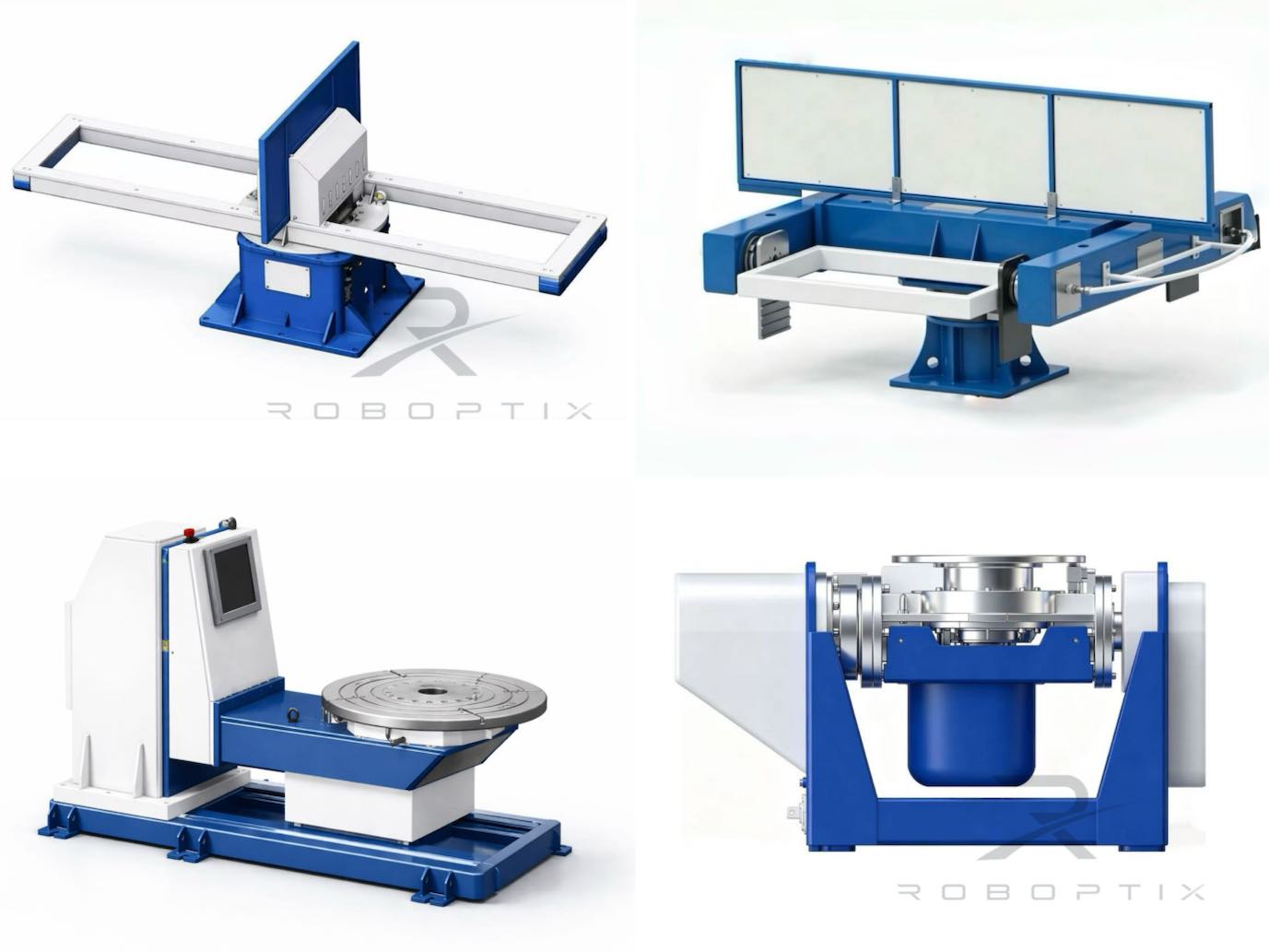
The conversion principle is universal, but the hardware differs by part shape. Headstock-tailstock units (ROBOPTIX B001–B004) suit long beam-like members rotated about a horizontal axis. L-type tilt-turn positioners add a tilt axis for plate work needing access to multiple faces without re-fixturing. U-type dual-column units support very large, heavy fabrications — common in wind-tower and pressure-vessel production — where both ends require support. Selecting the correct geometry ensures the part can actually be brought to flat position for every joint, which is the entire point of the exercise.
4. Measurable Quality Gains
The quality improvement from position conversion is not theoretical. Typical outcomes after integrating a positioner into a robotic welding cell:
| Metric | Manual / No Positioner | With Positioner |
| First-pass yield | 70–85% | 95–98% |
| Overhead weld defects | High (baseline) | Near-zero (converted to 1G) |
| Travel speed (avg) | Baseline | Up to 1.4× faster |
| Crane moves / shift | 15–30 | 1–3 |
For code-critical work — pressure vessels under ASME Section VIII, or structural connections under AWS D1.1 — the difference between a 75% and a 97% first-pass yield translates directly into inspection costs, repair labor, and delivery risk.
4.1 A Worked Example
Consider a fabricator welding 500 identical bracket assemblies per month, each with four fillet welds. Welded manually in mixed positions, assume a 78% first-pass yield and 25 minutes of crane-dependent repositioning per unit. Converting to a positioner cell at 96% yield with one-minute loading eliminates roughly 120 hours per month of repositioning downtime and cuts repair welding by more than half. The quality gain and the throughput gain compound — fewer repairs means more capacity for new orders, not just cleaner parts. This is why position conversion regularly appears at the top of ROI justifications for robotic welding cells, independent of the labor savings that dominate most business cases.
5. Robot Integration Multiplies the Benefit
When the positioner is integrated as a robot external axis (via EtherCAT or a controller-native interface), the quality gain compounds:
- Synchronized motion: The robot and positioner move as one kinematic chain, keeping the torch at a constant optimal angle throughout the weld.
- Repeatability: ROBOPTIX servo positioners hold angular position to ±0.05 mm at R350 — roughly 0.008° — so every part is welded in the identical, gravity-favorable orientation.
- Operator independence: Quality no longer depends on an individual welder’s ability to manage an overhead pool. The positioner makes the easy position the only position.
6. When You May NOT Need a Positioner
Demands honesty: a positioner is not always the right investment. You may not need one if:
- Your parts are small and can be hand-positioned into flat orientation cheaply
- Production volume is low and crane repositioning downtime is acceptable
- All your welds are already naturally accessible in flat or horizontal position
If, however, you routinely weld large, heavy, or multi-face parts — or you are pursuing robotic welding certification for code work — position conversion is the highest-leverage change you can make.
Frequently Asked Questions
Q: What does 1G, 2G, 3G, 4G mean in welding?
A: They are AWS/ASME welding positions describing joint orientation relative to gravity. 1G is flat (easiest), 4G is overhead (hardest). Each step up means gravity works harder against the molten pool, increasing defect risk.
Q: How much does a welding positioner reduce defects?
A: In ROBOPTIX field deployments, converting overhead and vertical welds to flat position has raised first-pass yield from roughly 70–85% to 95–98%, with overhead-weld porosity dropping toward zero. Results vary by process and material.
Q: Can a positioner weld pipe in 6G position?
A: A positioner doesn’t make you weld in 6G — it lets you avoid it. By rotating the pipe, the joint is held at the optimal angle (effectively 1G) for the entire seam, eliminating the need to traverse difficult fixed positions.
Q: Is a positioner worth it for small parts?
A: Usually not. For small parts that can be manually flipped into flat position, the crane-repositioning problem a positioner solves doesn’t exist. Positioners pay off with large, heavy, or multi-face weldments where repositioning is slow, crane-dependent, or physically unsafe.
Q: Does position conversion help with robotic welding specifically?
A: Yes — even more than with manual welding. A robot executes a programmed path with fixed parameters; if the joint is out of position, the robot cannot “compensate” the way a skilled welder might. Integrating the positioner as a synchronized external axis lets the robot weld every joint flat, making quality consistent and independent of part complexity.
Need help converting your overhead welds to flat?
Contact ROBOPTIX for a free positioner selection analysis based on your actual part geometry and production volume.
About the Author
Experience & Credentials
Robotic welding system integration specialist with 12+ years of direct project experience focused on Robot Positioner selection and integration. Has provided consulting to 300+ factories across North America, Europe, and Asia. All specification data in this article is drawn from actual H / B / L / U series product datasheets.
Company background: 26+ years of welding automation engineering, 40+ active patents, 1,500+ completed projects globally, approximately 70% involving Robot Positioner integration.
Certifications
- ISO 9001: 2015 (GB/T 19001-2016) — Quality Management System
- GJB 9001C-2017 — Military/Weapon Equipment Quality Management System
- EU CE — Machinery Directive 2006/42/EC (Cert. No. M.2026.206.C134866)
- High-Tech Enterprise — Cert. No. GR202341000595 (Issued Nov. 2023)
Last updated: Jun 2026
RELATED POSTS
Installation & Maintenance Guide for Robotic Laser Welding Systems: A Practical Roadmap
5 Reasons Large Workpiece Welding Is Inefficient — and How a Robot Positioner Solves Each One
No-Programming Robotic Welding Cell:How Vision-Guided Systems Eliminate Teach Pendants
7th Axis Robot vs Traditional Gantry: Which Is Better for Your Welding or Material Handling Line?
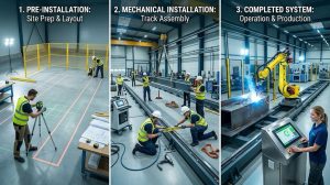
How to Install and Integrate a 7th Axis Robot: Step-by-Step Guide & Best Practices