Custom Robot Workstations And Laser Systems Manufacturer


Head-and-Tailstock vs. L-Type vs. U-Type Robot Positioner: How to Choose by Workpiece Shape
Start With the Workpiece, Not the Machine
The most common question we receive from factories evaluating Robot Positioners is: “Which is better — head-and-tailstock or U-type?” The question itself is framed incorrectly. The right question is: what does my workpiece look like, and which positioner is designed for it?
A head-and-tailstock is the optimal solution for pressure vessel shells — and nearly useless for automotive brackets. A U-type excels on multi-face components in the 300–1,000 kg range — and cannot handle a 3-meter pipe at any payload rating. This article approaches selection the way a buyer actually thinks: starting from the workpiece. For each of six common workpiece categories, we identify the right positioner type, explain why, and back it with documented production outcomes from real installations.
| Relationship to the full selection guide: This is the fast-decision companion to the 2026 Robot Positioner Buyer’s Guide: All 5 Types Compared. If you want deeper technical detail on each type, see that article. This one gets you to a recommendation in under 10 minutes. |
Quick-Match Table: Find Your Workpiece Category
The large majority of industrial welding workpieces fall into one of six categories. Locate yours below:
| Workpiece Description | Typical Examples | First Choice | Second Choice | Eliminate |
| Long, tubular, axially symmetric — both ends grippable | Pressure vessels, shafts, tower sections, pipe spools | Head-and-Tailstock (B Series) | H-Type (circular section) | U-Type, Three-Axis |
| Disc, ring, or planar geometry — low height-to-diameter ratio | Flanges, circular frames, EV battery trays | H-Type Rotation Table (H Series) | Head-and-Tailstock (small) | Three-Axis |
| Multi-face, 300–1,000 kg, pure welding | Automotive brackets, instrument frames, equipment mounting plates | U-Type Dual-Axis (U Series) | L-Type | Head-and-Tailstock |
| Multi-face, 300–1,500 kg, welding + assembly at same station | EV battery pack frames, motorcycle frames, aluminum structures | L-Type Dual-Axis (L Series) | U-Type | Head-and-Tailstock |
| Complex multi-face, 500–2,000 kg, heavy weldments | Excavator booms, crane jibs, wind turbine nacelle frames | Three-Axis (B008–B012) | Head-and-Tailstock (boom body) | H-Type, U-Type |
| Overweight workpiece, >2,000 kg | Heavy pressure vessels, large structural nodes, industrial frames | Heavy Head-and-Tailstock (B004) | Three-Axis (B008, up to 2,000 kg) | U-Type, light H-Type |
Scenario 1: Long, Tubular, or Axially Symmetric Workpieces
| Recommended: Head-and-Tailstock Robot Positioner (B Series) |
| Typical workpieces: Pressure vessel shells (ring and longitudinal seams), large drive shafts, wind turbine tower sections, engineering machinery boom tubes, pipe manifolds Core challenge: Manual repositioning of a 1,500 kg pressure vessel shell requires a crane and two riggers per flip, averaging 20 minutes per event. A typical shell needs 6 to 8 repositioning events per cycle — over 2 hours of lost arc time per component. Recommended type: Head-and-Tailstock Robot Positioner — B001 / B002 / B004 Why: The positioner rotates the workpiece continuously along its primary axis while the robot tracks the seam — a perfect geometric match for circumferential welds. Arc-on time reaches 85%+. Every seam is completed in flat position. Reference models: MRK-B001 (500–1,000 kg, 0.05 mm@R350, 90°/s, span 2–3.5 m) / MRK-B002 (1,000–1,500 kg, 60°/s) / MRK-B004 (1,500–5,000 kg, ±0.075 mm@R500, span up to 8 m) Documented result: A Gulf Coast pressure vessel fabricator using MRK-B002: porosity rate on ring seams dropped from 9.2% to 0.6%; throughput increased from 3 to 7 components per shift; annual rework cost reduction of $142,000. |
When head-and-tailstock does NOT fit
- Workpiece ends cannot be gripped concentrically (irregular cross-section, severe taper)
- Center of mass is significantly offset from the rotation axis — creates dangerous rotational dynamics
- Workpiece outer diameter exceeds the model’s maximum swing diameter
Scenario 2: Disc, Ring, or Planar Workpieces
| Recommended: H-Type Servo Rotation Table (H Series) |
| Typical workpieces: Flanges of all sizes, circular structural frames, EV battery pack base trays, circular end caps, ring sections Core challenge: Manually indexing a 600 kg flange between bolt-hole weld positions takes 3 to 5 minutes per index, introduces angular error, and creates fatigue over a full shift. Recommended type: H-Type Servo Rotation Table — H001 / H004 / H005 Why: The circular table rotates to each indexed position with servo precision (±0.05 mm) while the workpiece lies flat — matching the natural orientation of disc and planar parts. No lifting or tilting required; lowest integration cost of all five types. Reference models: MRK-H001 (500–2,000 kg, ±0.05@R350, 60°/s, table dia. 600–2,000 mm) / MRK-H004 (500–1,500 kg, max swing ø2,000 mm) / MRK-H005 (1,500–2,000 kg, max swing ø3,000 mm) Documented result: A flange fabrication shop using MRK-H001: single-shift flange output increased from 24 to 47 units (+96%); first-pass inspection pass rate improved from 71% to 97%. |
When H-type does NOT fit
- Workpiece requires welding on side faces or the underside — H-type rotation only exposes the top surface
- Workpiece height-to-diameter ratio exceeds 0.8 — rotational stability degrades, increasing risk
Scenario 3: Multi-Face Components, 300–1,000 kg, Pure Welding
| Recommended: U-Type Dual-Axis Robot Positioner (U Series) |
| Typical workpieces: Automotive suspension brackets, chassis mounting plates, instrument panel frames, body-in-white sub-assemblies, equipment housing weldments Core challenge: With a fixed fixture, 40–60% of weld joints on a four-face bracket are executed in vertical or overhead positions. The result: porosity at 8–12%, bead irregularity on vertical seams, and shift-to-shift inconsistency — all caused by position, not programming. Recommended type: U-Type Dual-Axis Robot Positioner — U001 / U002 Why: The J1 flip axis (±90°) and J2 rotation axis (±200°) bring any face to the upward flat-welding position before each weld sequence. The robot never welds out of position. Footprint of ~1.2 m² allows multiple units side by side in a single cell. Reference models: MRK-U001 (300 kg, ±0.05 mm@R250, J1: 30°/s / 2,695 N·m, J2: 60°/s / 1,225 N·m) / MRK-U002 (500–1,000 kg, flip ±0.075 mm@R500, tooling ±0.05 mm@R350, J2: 60°/s) Documented result: A Tier-2 automotive bracket supplier using two MRK-U002 units: overall defect rate dropped from 11.4% to 1.8%; monthly rework labor cost fell from $28,400 to $4,100; full investment recovered in 6.1 months. |
When U-type does NOT fit
- Workpiece weight exceeds 1,000 kg (U002 payload ceiling) — step up to L-type or three-axis
- Workpiece length exceeds the U-frame internal clearance — interference with the frame
- A simultaneous assembly operation is required at the same station — U-type has no assembly indexing function
Scenario 4: Multi-Face Components with Welding + Assembly at the Same Station
| Recommended: L-Type Dual-Axis Robot Positioner (L Series) |
| Typical workpieces: EV battery pack frames (aluminum and steel), motorcycle and bicycle main frames, mid-size equipment base structures, any workpiece requiring nut insertion, bearing press-fit, or part assembly at the welding fixture Core challenge: Transferring a 1,200 kg battery pack frame between a welding and an assembly station adds 15 to 20 minutes of non-value-added time per cycle, requires a crane lift each way, and introduces positional error at every transfer. Recommended type: L-Type Dual-Axis Robot Positioner — L001 / L002 Why: The L-frame tooling axis serves dual purpose: rotating the workpiece for multi-face welding access and indexing to precise positions for assembly. Both operations happen at the same fixture, eliminating inter-station transfer. L002 flip torque of 6,720 N·m handles heavily asymmetric 1,500 kg aluminum frames. Reference models: MRK-L001 (300–500 kg, tooling axis ±0.05 mm@R350, flip ±0.075 mm@R500, rotation 60°/s) / MRK-L002 (1,500 kg, rotation torque 3,960 N·m, flip torque 6,720 N·m, welding ground cable ≥75 mm²) Documented result: An EV battery pack manufacturer using MRK-L002: single-unit cycle time reduced from 42 to 28 minutes (−33%); two assembly transfer stations eliminated; annual labor cost saving of $186,000. |
When L-type does NOT fit
- Pure welding application with no assembly requirement — U-type usually offers better cost efficiency
- Application requires flip angle greater than 90° — L-type flip axis travel is limited
Scenario 5: Complex Heavy Weldments, 500–2,000 kg
| Recommended: Three-Axis Robot Positioner (B008–B012 Series) |
| Typical workpieces: Excavator boom arms and dippers, crane jib sections and slewing rings, wind turbine nacelle base frames, mining equipment main structures, port machinery rotating assemblies Core challenge: A complex excavator boom has seams across 6+ planes. Traditional workflow requires 4 to 6 crane repositioning events per cycle, averaging 22 minutes each. Total repositioning time per boom: 90 to 130 minutes before any additional welding. Recommended type: Three-Axis Robot Positioner — B009 / B011 / B008 Why: Three coordinated servo axes bring any seam on any face to flat-welding position in sequence. The workpiece is loaded once and unloaded once — all face repositioning is handled by the positioner. B008 swing reaches 5,000 mm; B009 and B011 achieve ±0.03 mm repeatability. Reference models: MRK-B008 (1,500–2,000 kg, rotation ±0.05 mm@R500, swing ø5,000 mm, tooling 60°/s) / MRK-B009 (500–1,000 kg, rotation ±0.03 mm@R500, tooling 90°/s) / MRK-B011 (1,000–1,500 kg, rotation ±0.03 mm@R500, tooling 90°/s) Documented result: A construction machinery factory using MRK-B011 on excavator boom production: crane operations per shift reduced from 68 to 8 (load-in/out only); single-unit welding cycle shortened from 4.2 to 2.7 hours (−36%); annual output increased from 580 to 890 units. |
When three-axis does NOT fit
- Workpiece exceeds 2,000 kg — switch to heavy-duty head-and-tailstock (B004: 5,000 kg capacity)
- Workpiece is a standard cylinder or disc — three-axis complexity and cost is not justified; use head-and-tailstock or H-type
Scenario 6: Overweight Workpieces — Above 2,000 kg
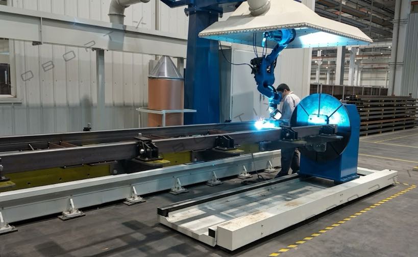
| Recommended: Heavy-Duty Head-and-Tailstock Robot Positioner (MRK-B004) |
| Typical workpieces: Heavy pressure vessel assemblies (diameter 2 m+), large storage tank sections, heavy industrial structural nodes, massive cast-and-weld assemblies Core challenge: At payloads above 2,000 kg, most Robot Positioner types are out of specification. The engineering challenge becomes drive torque, braking force, and span rigidity at high rotational inertia — not just nominal load rating. Recommended type: Heavy-Duty Head-and-Tailstock — MRK-B004 Why: Rated for 1,500 to 5,000 kg with spans from 3 m to 8 m, designed for high-inertia dynamics of overweight cylindrical workpieces. Controlled deceleration at 20°/s² prevents workpiece shift. The only standard-catalogue model covering loads above 2,000 kg in continuous production. Reference models: MRK-B004 (1,500–5,000 kg, ±0.075 mm@R500, max flip speed 30°/s, accel/decel 20°/s², standard spans: 3 / 5 / 6 / 8 m) Documented result: A heavy industrial manufacturer using MRK-B004 (8 m span) on 4.2-tonne storage tank sections: crane repositioning events per shift reduced from 12 to 0 mid-cycle; welding efficiency increased 44%; all crane-related safety incident records eliminated for that workstation. |
Head-and-Tailstock vs. L-Type vs. U-Type: Direct Comparison
These three types generate the most selection questions. Five-dimension decision table:
| Dimension | Head-and-Tailstock (B) | L-Type Dual-Axis (L) | U-Type Dual-Axis (U) |
| Workpiece shape fit | ❌ Axially symmetric only | ✅ Multi-face, mid-size | ✅ Multi-face, small–mid |
| Maximum payload | ✅ 5,000 kg (B004) | ⚪ 1,500 kg (L002) | ❌ 1,000 kg (U002) |
| Eliminates overhead welding | ⚪ Circumferential seams only | ✅ Multi-face effective | ✅ All faces — J1+J2 |
| Assembly function at same station | ❌ Not supported | ✅ Tooling axis dual-purpose | ❌ Not supported |
| Floor footprint | ❌ Large (span 2–8 m) | ⚪ Medium | ✅ Smallest (~1.2 m²) |
| Integration complexity | ✅ Low (single axis) | ⚪ Medium (two axes) | ⚪ Medium (two axes) |
| Typical purchase cost | ⚪ Mid | ⚪ Mid | ⚪ Mid |
| Best industry fit | Pressure vessels, wind, pipe | EV battery, motorcycle, aluminum | Automotive brackets, BIW |
⚪ = Middle range between the two extremes.
5 Questions to Confirm Your Selection
| Q1: Can both ends of the workpiece be gripped concentrically? → Yes: head-and-tailstock is a candidate. No: eliminate head-and-tailstock. Q2: Does the workpiece weight (including fixture) exceed 1,000 kg? → Yes: eliminate U-type; evaluate L-type, head-and-tailstock, or three-axis. Q3: Does the workpiece require welding and assembly operations at the same station? → Yes: L-type is the primary candidate. Q4: Are weld seams distributed across 4 or more faces? → Yes: eliminate head-and-tailstock and H-type; evaluate U-type, L-type, or three-axis. Q5: Is annual volume above 500 units with strict weld position consistency requirements? → Yes: coordinated axis control is mandatory, not optional — confirm robot brand compatibility before ordering. |
Not Sure Which Category Your Workpiece Falls Into?
Send us a workpiece drawing or photograph with the weight and monthly production volume. Our engineering team will identify the right Robot Positioner type, specify the correct model, and provide a preliminary ROI estimate — in writing, within 24 business hours, at no cost.
► Submit your workpiece details for a free selection recommendation
About the Author
| Experience & Credentials Robotic welding system integration specialist with 12+ years of direct project experience. The workpiece-scenario framework in this article is based on selection consulting delivered to 300+ factories across North America, Europe, and Asia. All case study data reflects documented, anonymized production records from actual installations. Company: 26+ years of welding automation engineering, 40+ active patents, 1,500+ completed projects globally. All product specifications drawn from current H / B / L / U series datasheets. Certifications: ISO 9001:2015 (GB/T 19001-2016) — Quality Management System GJB 9001C-2017 — Military/Weapon Equipment Quality Management System EU CE — Machinery Directive 2006/42/EC (Cert. No. M.2026.206.C134866) High-Tech Enterprise — Cert. No. GR202341000595 (Issued Nov. 2023) Last updated: May 2026 |
RELATED POSTS
8 Costly Mistakes When Deploying a Robotic Welding Cell (And How to Avoid Them) – 2026 Edition
7th Axis Robot Track System Maintenance & Troubleshooting Guide
Round vs Rectangular vs Irregular: Matching Welding Positioner Configuration to Workpiece Geometry
Backlash, Stiffness, and Thermal Drift: The Three Hidden Specs That Define Welding Positioner Performance
Manual vs Robotic Welding for Structural Steel:When Does Automation Pay Off?