


Custom Robot Workstations And Laser Systems Manufacturer


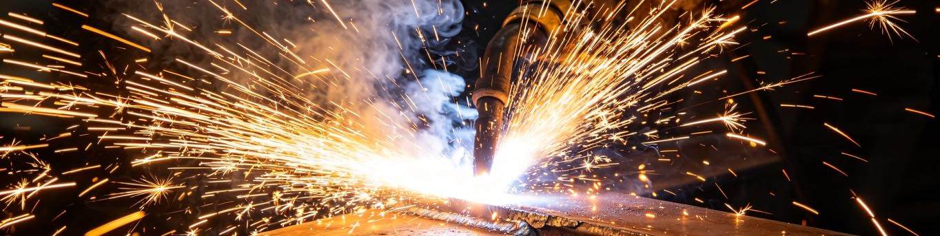
What Is a No-Teach Robotic Welding Cell


PRODUCT PARAMETERS
Description
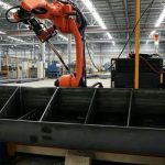
A No-Teach Robotic Welding Cell is an intelligent welding automation system that eliminates the need for traditional manual teach pendant programming. By integrating 3D vision sensing, intelligent weld recognition, and automatic path planning technologies, the system can automatically generate welding programs and execute welding tasks without the time-consuming “point-by-point” teaching process typically required for industrial robots.
Traditional robotic welding requires operators to manually guide the robot through each welding path, a process that can take hours or even days for complex workpieces. Teaching-less technology fundamentally changes this paradigm. The robot “sees” the workpiece, automatically identifies weld seams, plans the optimal welding trajectory, and executes the weld — all without manual programming.
Teaching-less robotic workcells operate under demanding industrial conditions including varying workpiece fit-up, inconsistent part positioning, welding spatter, and thermal distortion. Therefore, they are designed with high-precision 3D cameras, advanced vision algorithms, rigid robotic platforms, and intelligent control systems to ensure stable performance and reliable weld quality.
These workcells are widely used in various applications including steel structure fabrication, construction machinery, railway components, shipbuilding, and general manufacturing — particularly in high-mix, low-volume production environments where traditional robotic programming would be impractical.
System Specifications (FSWELD 3800E)
Based on the Bochuc FSWELD 3800E intelligent welding control system, the teaching-less robotic workcell meets the following technical boundaries:
| Parameter | Specification |
| Workpiece width | ≤ 3000mm |
| Rib height | 40mm ~ 1000mm |
| Rib thickness | 6mm ~ 30mm (uniform per plate) |
| Rib length | ≥ 30mm |
| Perpendicular deviation (rib to base plate) | ≤ 5° |
| Rib spacing (along scanning direction) | ≥ 200mm |
| Depth-to-width ratio | ≤ 1.5 (for obstacle avoidance) |
| Upper edge inclination of vertical plate | ≤ 45° |
| Angle between two intersecting plates | ≥ 30° |
| Workpiece placement height difference | ≤ 10° |
| Web plate bending | ≤ 30mm |
| Vertical plate bending | ≤ 20mm |
| Weld hole size | 25mm ~ 50mm |
| Assembly tolerance | ≤ 30mm |
| Assembly angle deviation | ≤ 8° |
| Weld length variation tolerance | ≤ 30mm |
| Gap tolerance (fillet weld Z≥8mm) | ≤ 3mm |
| Groove dimension consistency | ±1mm |
| Groove angle deviation | 0° ~ -5° |
Structure of a Teaching-less Robotic Workcell
A typical teaching-less robotic workcell consists of several key components:
- Industrial robot with welding torch (supporting KUKA, FANUC, YASKAWA, QJAR, EFORT, etc.)
- 3D vision system (BCW181P line laser stereo camera)
- Laser seam seeker (BCW600P-E wire seeker)
- Teaching-less control system (FSWELD 3800E industrial PC)
- Workpiece positioning system (turntable, headstock-tailstock, positioner, rail, gantry)
- Safety enclosure and fume extraction
- Operator interface with digital twin visualization (WKB SW welding teach pendant)
Among these components, the3D vision system and intelligent control softwareplay the most critical role, enabling the robot to perceive, understand, and adapt to the actual workpiece without human intervention.
3D Vision System (Reverse Modeling)
The 3D vision system is the “eye” of the teaching-less robotic workcell. The FSWELD 3800E system is equipped with theBCW181P line laser stereo camera, supportingreverse modeling— the ability to scan workpieces and generate 3D models without CAD input.
Camera installation requirements:
- Mounting height: 1.7m from lens lower surface to processing plane
- Mounting orientation: Must be parallel to the ground
Two operation modes:
- Reverse Modeling (3800 series): Scan workpieces directly without CAD models
- Model-Driven (2800/3800 series): Import STEP/IGES/DXF models for automatic path generation
A high-quality 3D vision system must provide:
- Fast scanning speed (typically 30-60 seconds per workpiece)
- High resolution for accurate seam detection (error <0.16mm)
- Robustness against ambient light and welding spatter
- Ability to detect multiple joint types (butt, fillet, lap, corner, pipe-plate)
- Automatic compensation for part fit-up variations (within ±30mm)
Teaching-less Control System
The teaching-less control system is the “brain” that processes visual data and generates robot motion programs automatically. The FSWELD 3800E system uses theHypTronic3_HPC3870E-W industrial PCwithHPL2720E/BCL4500B adapter boards.
The operator simply loads a 3D CAD model (STEP, IGES, or DXF format) or uses reverse modeling to scan the workpiece, identifies the weld joints to be completed, and selects basic parameters such as joint type and welding technique.
The control system then performs the following functions automatically:
| Function | Description |
| 3D model parsing / reverse modeling | Extracts geometry from CAD or generates from scan |
| Automatic path planning | Generates optimal robot trajectory with collision avoidance |
| Weld parameter matching | Selects appropriate voltage, current, speed, and weave parameters |
| Digital twin simulation | Visualizes entire welding process before execution |
| Real-time adaptation | Adjusts torch position based on actual seam detection |
| Intelligent arc tracking | Real-time deviation correction during welding (±8° angle deviation) |
A high-quality teaching-less control system must provide:
- Support for common CAD formats (STEP, IGES, DXF)
- Tekla one-click extraction
- Automatic recognition of weld joint types
- Intuitive user interface requiring minimal training
- Digital twin visualization for program verification
- Adaptability to various welding processes (GMAW, GTAW, pulsed MIG)
Laser Seam Detection System (Seeker)
In addition to 3D vision for part location, the FSWELD 3800E system incorporates theBCW600P-E wire seekerdedicated to precise seam detection. This system scans the actual weld joint, compares the measured data to the CAD model, and makes micro-adjustments to the welding path in real-time.
BCW600P-E improvements over standard BCW600P:
- Optimized for galvanized pipes, aluminum parts, ground workpieces, and thin-plate lap joints
- Effectively solves precision positioning failures caused by point cloud loss
- Additional support for aluminum and stainless steel reflective materials
- Supports ground weld areas (ground area ≤20mm on vertical and base plates)
Cable requirement: Standard Ethernet cable + high-flex拖链 hybrid cable, total length ≤50m.
A high-quality laser seam detection system must provide:
- Non-contact measurement for high speed (as little as 15 seconds for typical joints)
- Sub-millimeter accuracy for critical applications
- Real-time feedback to robot controller
- Robust operation in welding environment
- Automatic compensation for part fit-up variations
Workcell Configurations
Teaching-less robotic workcells can be configured in various layouts to suit different applications:
| Configuration | Description | Best For |
| Floor-mounted robot with turntable | Robot on fixed pedestal, workpiece rotates on single-axis positioner | Medium-sized parts requiring multiple weld positions |
| Robot on 7th axis rail | Robot travels along linear rail to access multiple stations or long workpieces | Large workpieces or multi-station cells |
| Headstock-tailstock positioner | Long workpieces clamped and rotated between headstock and tailstock | Beams, columns, shafts, and structural members |
| Overhead gantry configuration (8/9 axis) | Robot inverted on gantry for large, heavy workpieces | Bridge girders, ship panels, large structures |
| Dual-station workcell | Two workpiece positions allowing loading/unloading while robot welds | High-productivity, reduced idle time |
Supported Robot Configurations: 6-axis, 7-axis (floor/overhead rail), 8-axis (YX type), 9-axis (YXZ/YZX type)
Working Envelope(with 2m reach robot):
- Fixed base: Max width 1200mm, max length 2000mm
- Rail + floor mount: Max width 1200mm, length limited by rail
- Rail + overhead mount: Max width 2200mm, length limited by rail
Supported Industries and Workpiece Types
Teaching-less robotic workcells are widely used across various industries. Below are verified applications:
1. Building Steel Structures
| Type | Features |
| H-beam flanges, linear ribs | Base plate with two side flanges, variable width, multiple ribs allowed |
| Irregular curved vertical plates | Supports circular and irregular curved plates |
| Irregular ribs | Higher or lower than flange, supports parallel, convex, concave |
| Inclined ribs | Size ≥100×100mm, angle 60°~120°, thickness <15mm |
| End caps | Triangular reinforcement, side length ≥40mm, thickness ≥6mm |
| Support plates | Thickness ≥10mm, area ≥50×50mm |
2. Bridge and Shipbuilding
| Type | Features |
| T-bars | Vertical plate with inclined or notched upper edge, weld holes ≥25mm |
| Sub-assemblies | Supports parallel, upward/downward curved vertical plates |
| Plate units | Polygonal or elliptical holes, rib height ≥40mm |
3. Transformer Tanks
| Type | Features |
| Plate ribs | Thickness ≥6mm, height ≥40mm, slope requires 20mm height margin |
| Sealing flanges | Thickness ≥10mm, length/width ≥50mm, rectangular (no circles), chamfer radius ≥5mm |
| Small ribs | Triangular reinforcement, side length ≥40mm, thickness ≥6mm |
4. Tower Foot Structures
- Dedicated tower foot mode (inherited from 2800T)
- Automatic drawing generation, 2D to 3D conversion
Not Supported
- Mirror-reflective workpieces (stainless steel/aluminum require evaluation)
- Side-mounted plates
- Circular flanges
- Aluminum alloys (no arc tracking, reflection issues)
- Stainless steel not fully tested by FSWELD system
Supported Welding Processes
| Parameter | Specification |
| Materials | Carbon steel, low alloy steel, stainless steel (non-mirror) |
| Welding method | Gas Metal Arc Welding (GMAW) |
| Welding positions | PA, PB, PC, PF, PG |
| Shielding gas | 80%Ar+20%CO₂, 100%CO₂, 95%Ar+5%O₂ |
| Wire diameter | Solid φ1.0/1.2/1.6mm, flux-cored φ1.2mm |
Process Software Package Support:
- Scratch start/re-start
- Weave welding (sine, triangle, L-shape, inclined sine, pendulum)
- Intermittent welding (skip welding, back-step welding)
- Corner welding
- Continuous welding
- Weld hole welding
- Arc tracking (sine/L-shape/triangle weave)
- Multi-layer multi-pass welding
- Box column groove adaptation
Manufacturing Process
Teaching-less robotic workcells are produced through several key manufacturing processes:
Design and Engineering: Custom cell design based on workpiece size, material, and production requirements.
Fabrication and Assembly: High-strength steel structures for positioners, rails, and safety enclosures.
System Integration: Integration of robot, vision system, controller, and positioners.
Software Configuration: Calibration of vision system, configuration of welding parameters, and setup of user interface.
Testing and Calibration: Full system testing including vision calibration, path verification, and weld quality validation.
Operator Training: Training on system operation, basic troubleshooting, and maintenance procedures.
Key Benefits
| Benefit | Description |
| Eliminates teach pendant programming | No programming skills required; operators can be trained in hours |
| Reduces programming time by 70-90% | From hours/days to minutes |
| No custom fixturing required | Workpieces can be tack-welded and placed in simple clamps (assembly tolerance ±30mm) |
| Handles part variation | Automatically compensates for fit-up and positioning differences (angle deviation ≤8°) |
| Ideal for high-mix production | Switch between different parts without reprogramming |
| Digital twin verification | Simulate entire weld before execution |
| Lower skilled labor requirement | Reduces dependence on expert welders and programmers |
| Reverse modeling capability (3800 series) | Generate welding paths without CAD models |
| Intelligent arc tracking | Real-time deviation correction during welding |
Custom Robot Workstations & Laser Systems Manufacturer
Industrial Robotic Automation Solutions
We deliver high-performance robotic automation solutions for modern manufacturing.
Specializing in robot workstations and laser systems, we provide customized solutions for welding, cutting, laser processing, and material handling applications. With 26+ years of expertise, 40+ patented technologies, and 2,000+ successful projects worldwide, we empower manufacturers to increase productivity, ensure consistent quality, and maximize ROI.
Supported by an experienced engineering team and an ISO-certified production base, we are dedicated to helping our customers stay competitive in a rapidly evolving global market.